
2026-05-18
Content
Flow control valves regulate the rate, direction, and pressure of fluid moving through a system. Choosing the wrong type leads to inefficiency, equipment damage, or complete system failure. The most commonly used flow control valve types include needle valves, ball valves, butterfly valves, globe valves, gate valves, check valves, and pressure-compensated flow control valves — each designed for specific applications and operating conditions. Understanding what sets them apart is the fastest way to make the right selection.
In industrial settings, a poorly matched valve can account for up to 30% of total energy losses in a hydraulic or pneumatic circuit. In water treatment plants and chemical processing facilities, valve selection directly impacts throughput, safety compliance, and maintenance frequency. This guide covers the primary types of flow control valves, their mechanisms, real-world applications, and the key performance data you need to compare them accurately.
A flow control valve is a device used to manage the volume of fluid — liquid, gas, or slurry — passing through a pipeline or system per unit of time. Unlike shut-off valves that simply open or close a passage, flow control valves modulate the flow rate continuously or in stepped increments depending on their design.
The fundamental mechanism involves varying the cross-sectional area of the flow path. When the opening is large, resistance drops and flow increases. When the opening narrows, resistance increases and flow decreases. The relationship between valve opening and flow rate is not always linear — different valve designs produce different flow characteristics, referred to as "inherent flow characteristics," which include linear, equal percentage, and quick-opening curves.
Flow control valves operate across a wide range of pressures — from under 1 bar in low-pressure pneumatic systems to over 700 bar in high-pressure hydraulic circuits found in industrial presses and subsea equipment. They also handle temperatures ranging from cryogenic conditions (-196°C for liquefied gas applications) up to 650°C in steam systems.
Modern valve designs incorporate actuators — manual handwheels, pneumatic actuators, electric motors, or hydraulic cylinders — to enable remote or automated control. In process industries, flow control valves are often paired with flow meters and PID controllers to maintain a set flow rate automatically.
Needle valves are among the most precise flow control valves available for low-flow applications. They use a slender, tapered needle-shaped plunger that seats into a matching orifice. Rotating the stem advances or retracts the needle, creating fine adjustments to the flow area.
Needle valves are capable of flow coefficients (Cv) as low as 0.001, making them ideal for calibration lines, instrument purging, chemical dosing systems, and laboratory equipment. In hydraulic circuits, they're used to control actuator speed independently of load — commonly described as "meter-in" or "meter-out" configurations.
In pneumatic timing circuits, needle valves control the fill and exhaust rates of cylinders to set actuator speed. A single-turn adjustment can shift cycle time by several hundred milliseconds — critical in packaging machinery and automated assembly lines where throughput is tied directly to cycle speed.
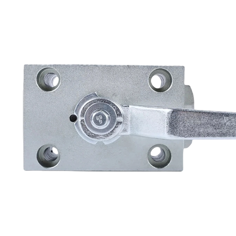
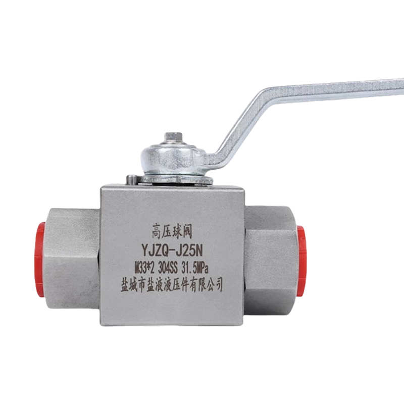
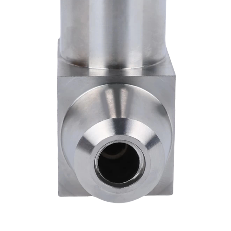
Ball valves use a spherical ball with a through-bore that rotates 90 degrees between the open and closed position. They are predominantly used as on/off valves, but certain designs — specifically characterized ball valves and V-port ball valves — are engineered specifically for flow control.
Standard full-bore ball valves should not be used for continuous throttling. When the ball is held in a partially open position, the high-velocity flow through the restricted gap causes erosion of the ball and seat, reducing sealing effectiveness over time. V-port ball valves address this limitation by shaping the port opening as a V-notch, which provides a more controllable and consistent flow characteristic across the travel range.
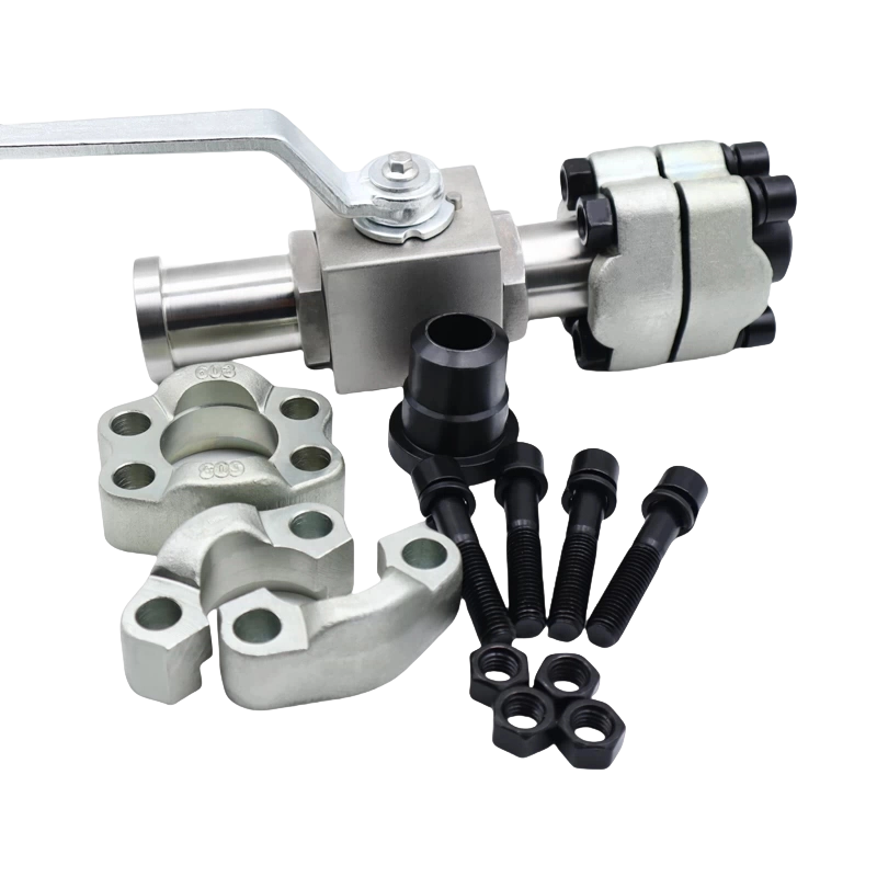
Ball valves are available in sizes from 1/4" up to 48" and larger. They handle pressures from vacuum to over 1,000 bar in subsea and wellhead applications. Operating torque is relatively low, making them easy to automate with quarter-turn pneumatic or electric actuators — a significant advantage in large-scale process plants.
In the oil and gas industry, ball valves dominate pipeline isolation. In water distribution networks, they function as zone isolation valves. When a ball valve is used for flow control specifically, it's almost always a V-port or characterized variant — plain full-bore designs are not appropriate substitutes.
Globe valves are the most widely used flow control valves in process industries where precise throttling is required. They use a plug (or disc) that moves perpendicular to the flow path, varying the gap between the plug and the seat ring. This design creates a tortuous flow path that produces higher pressure drop than ball or gate valves but enables excellent control.
Globe valves typically offer a rangeability of 50:1 to 200:1 — meaning they can accurately control flow from 0.5% to 100% of their rated capacity. This makes them suitable for applications requiring precise modulation over a wide range, such as steam control, fuel gas regulation, and cooling water systems.
The plug and seat geometry — collectively called the "trim" — determines the valve's flow characteristic:
Globe valves are also available in angle body configurations, where the inlet and outlet are at 90 degrees. This reduces the number of pipe bends needed and lowers overall pressure drop compared to standard straight-through globe bodies. Angle globe valves are particularly common in steam condensate systems.
One drawback is that globe valves create a significantly higher permanent pressure drop than ball or butterfly valves — sometimes two to five times higher. In systems where energy efficiency is the priority and precise control is secondary, this pressure loss penalty can be a deciding factor against globe valve selection.
Butterfly valves use a disc mounted on a rotating shaft at the center of the valve body. When the shaft rotates 90 degrees, the disc moves from fully perpendicular to the flow (closed) to fully parallel (open). Their compact, lightweight design makes them the valve of choice for large-diameter pipelines — sizes from 2" up to 200" are available.
For flow control applications, high-performance butterfly valves with offset disc designs are used instead of concentric types. A double-offset (high-performance) butterfly valve positions the disc shaft off-center both horizontally and vertically, reducing seat contact and wear during operation. Triple-offset butterfly valves add a third geometric offset to produce a cam-action sealing mechanism — enabling bubble-tight shutoff at full pressure ratings.
| Type | Offset Design | Typical Pressure Rating | Best For |
|---|---|---|---|
| Concentric | None | Up to 16 bar | Water, HVAC, general service |
| Double Offset | Shaft offset in two planes | Up to 50 bar | Process industries, oil & gas |
| Triple Offset | Cam-action geometry | Up to 150+ bar | High-pressure steam, LNG, refining |
Butterfly valves offer very low pressure drop in the fully open position — significantly lower than globe valves of comparable size. This makes them attractive for systems where energy efficiency matters, such as large water distribution networks, cooling tower circuits, and HVAC systems. A 24" butterfly valve handling 5,000 m³/h of water might have a pressure drop of just 0.2 bar fully open, compared to 1.5 bar or more for a comparable globe valve.
The control characteristic of a butterfly valve is inherently quick-opening in nature — a large portion of flow passes through even at moderate disc angles. This limits their effective throttling range to roughly 10–70 degrees of travel, with the most controllable zone between 20 and 60 degrees. Outside this range, control becomes difficult because small changes in position produce large changes in flow.
Gate valves operate by raising or lowering a flat gate across the flow path. They are designed exclusively for on/off isolation service and should never be used for flow control. When a gate valve is held in a partially open position, the high-velocity flow causes severe erosion of the gate and seat faces, rapidly degrading sealing performance.
Gate valves require multiple turns of the handwheel — often 20 or more — to move from fully open to fully closed, making them impractical for frequent or rapid actuation. They also have large face-to-face dimensions and are among the heaviest valve types per pipe bore, which increases installation and maintenance costs in large sizes.
Their primary advantage is extremely low pressure drop in the fully open position — the gate retracts completely out of the flow path, leaving an unobstructed bore. This makes them common in long-distance pipelines, water mains, and fire protection systems where minimizing friction losses over distance is critical. But for any application requiring flow modulation, a different valve type must be selected.
Check valves are automatic flow control valves that allow fluid to pass in one direction only. They open under forward flow pressure and close when flow reverses or pressure drops. No manual or actuated operation is needed — the valve responds entirely to fluid dynamics.
They are essential in pump discharge lines to prevent reverse rotation and water hammer when pumps shut down, in compressor outlet lines to protect against backflow, and in chemical dosing systems to prevent cross-contamination between process streams.
The cracking pressure — the minimum upstream pressure needed to open the check valve — is a critical specification. Most swing check valves crack open at 0.03 to 0.1 bar, while spring-loaded lift checks may require 0.2 bar or more. In low-differential-pressure systems, this cracking pressure can represent a meaningful portion of available driving head, affecting pump selection and system design.
In hydraulic systems, load variations cause pressure fluctuations that affect the flow rate through a simple orifice-type needle or throttle valve. A pressure-compensated flow control valve solves this problem by incorporating a pressure-reducing spool that maintains a constant pressure differential across a fixed orifice, regardless of upstream or downstream pressure changes.
A pressure-compensated valve can maintain flow rate accuracy within ±3–5% across pressure variations of 50–300 bar — far beyond what a simple needle valve can achieve. This is critical in applications like hydraulic press control, where consistent cylinder speed must be maintained regardless of varying resistance forces.
These valves are available in both inline (cartridge) and manifold-mounted configurations. Cartridge valves are threaded directly into machined cavities in hydraulic manifolds, reducing hose connections, weight, and potential leak points. In mobile hydraulic equipment — excavators, cranes, agricultural machinery — cartridge-mounted pressure-compensated valves are the standard approach.
Hydraulic oil viscosity changes significantly with temperature — typically by a factor of 3 to 10 between cold startup (0°C) and operating temperature (60°C). This viscosity change affects flow through the control orifice. Temperature-compensated flow control valves add a bimetallic or thermostatic element that adjusts the orifice size as temperature changes, maintaining a consistent flow rate from cold start through full operating temperature. These are used in aircraft hydraulic systems and precision machine tools where consistent performance across temperature ranges is non-negotiable.
Diaphragm valves use a flexible membrane (the diaphragm) that is pressed against a weir or seat to restrict or stop flow. The fluid contacts only the diaphragm and the valve body interior — no stem packing, no internal metal moving parts contact the process fluid. This design eliminates both the risk of process contamination from external sources and the risk of leakage to atmosphere.
Diaphragm valves are the standard choice in pharmaceutical manufacturing, biotechnology, food and beverage processing, and semiconductor fabrication — environments where contamination control is paramount. The smooth, crevice-free interior of a sanitary diaphragm valve can be cleaned-in-place (CIP) and sterilized-in-place (SIP) without disassembly, a major advantage in compliant production environments.
Diaphragm materials include EPDM, PTFE, and silicone, each suited to different fluid chemistries and sterilization methods. PTFE diaphragms handle highly aggressive chemicals — acids, solvents, oxidizers — that would destroy elastomeric materials. EPDM handles steam sterilization well and is commonly used in pharmaceutical bioprocessing.
The primary limitation is pressure and temperature rating: most diaphragm valves are rated to a maximum of 10–16 bar and 150°C, which is sufficient for pharmaceutical and food processing but excludes high-pressure industrial applications. Diaphragm valves are also limited to moderate flow control precision — they are not appropriate where fine throttling accuracy over a wide range is needed.
Plug valves use a cylindrical or conical plug with a through-port that rotates within the valve body. A 90-degree quarter-turn moves the plug between fully open and fully closed. In terms of operating mechanism and speed, they closely resemble ball valves, but differ in that the sealing surface is a large-area cylinder or cone rather than a sphere.
Lubricated plug valves inject a sealant into the plug-body interface, reducing friction and providing a secondary seal. This design handles heavy crude oil, bitumen, slurries, and fluids with suspended solids far better than ball valves with elastomeric seats. In petroleum refining, lubricated plug valves are the standard for crude unit isolation and vacuum tower bottoms service, where temperatures exceed 300°C and fluid viscosity is extreme.
Multi-port plug valves (three-way, four-way) offer the ability to divert flow between multiple lines using a single valve. This simplifies piping design in mixing, diverting, and blending applications. A single three-way plug valve can replace two or more conventional valves, reducing installed cost and potential leak points.
Solenoid valves use an electromagnetic coil to actuate a plunger that opens or closes an orifice. They are not inherently throttling devices — most operate as two-position (on/off) valves. However, pulse-width modulation (PWM) techniques allow solenoid valves to simulate proportional flow control by rapidly switching between open and closed states at varying duty cycles.
Proportional solenoid valves with a continuously variable plunger position are used in automotive fuel injection, medical equipment, and HVAC systems where precise, electrically controlled flow regulation is needed at high response speeds. Response times for solenoid valves range from 5 milliseconds for small direct-acting types to 100 milliseconds or more for large pilot-operated designs.
Solenoid valves are available in direct-acting and pilot-operated configurations. Direct-acting types open directly by electromagnetic force — they work even at zero differential pressure but are limited to small orifice sizes (typically up to 1/2"). Pilot-operated solenoid valves use a small pilot orifice to shift a larger main piston or diaphragm, enabling control of large flow areas without requiring large coil power — but they require a minimum differential pressure (typically 0.3–0.5 bar) to function.
Selecting the right valve type requires comparing multiple performance criteria simultaneously. The table below summarizes the key parameters for the primary flow control valve types discussed in this article.
| Valve Type | Throttling Ability | Pressure Drop (open) | Typical Size Range | Actuator Type | Primary Application |
|---|---|---|---|---|---|
| Needle | Excellent (fine) | High | 1/8"–2" | Manual | Instrumentation, hydraulics |
| Globe | Excellent | Medium–High | 1/2"–24" | Manual / Pneumatic / Electric | Process control, steam, chemical |
| Ball (V-port) | Good | Low | 1/2"–24" | Pneumatic / Electric | Slurry, pulp, viscous fluids |
| Butterfly (triple offset) | Moderate | Very Low | 2"–200" | Pneumatic / Electric | Large pipelines, HVAC, water |
| Diaphragm | Moderate | Medium | 1/4"–12" | Manual / Pneumatic | Pharma, food, biotech |
| Pressure-compensated | Excellent (constant flow) | Medium | Cartridge–2" | Manual / Hydraulic | Hydraulic circuits, mobile equipment |
No single valve type suits every application. The selection process should be systematic, working through a series of technical and operational criteria before arriving at a final choice.
The fluid being controlled is the starting point. Identify whether the fluid is clean liquid, gas, steam, slurry, or a two-phase mixture. Determine viscosity, temperature, density, and any corrosive or abrasive characteristics. A highly corrosive acid requires PTFE-lined or alloy-body valves. A slurry with 30% solids by weight rules out needle valves and globe valves with small trim clearances.
Valve body and trim materials must be rated for the maximum operating pressure and temperature, with appropriate safety margins. ASME B16.34 and EN 12516 are the primary standards governing valve pressure-temperature ratings. Cast iron bodies are limited to approximately 250°C and 25 bar; carbon steel extends to 425°C and 250 bar; austenitic stainless steel handles cryogenic temperatures down to -196°C and elevated pressures to 420 bar depending on class.
Calculate the minimum and maximum flow rates the valve must handle. The ratio of maximum to minimum controllable flow is the rangeability or turndown ratio. If the required turndown is 50:1 or higher, globe valves or characterized ball valves are the appropriate choice. If turndown below 10:1 is acceptable, butterfly valves or V-port ball valves may work. If flow must be held absolutely constant despite pressure variations, a pressure-compensated design is required.
Decide whether the valve will be manually operated, automatically controlled, or remote-actuated. Manual valves are the lowest cost but cannot participate in automated control loops. Pneumatic actuators respond quickly (under 1 second for small valves) and are intrinsically safe in explosive atmospheres. Electric actuators provide precise position control and easy integration with digital control systems but are slower and require electrical power at the valve location.
Valve body weight, face-to-face dimension, and in-line maintainability affect total installed cost significantly. A 12" globe valve weighs 400–600 kg and has a face-to-face length of 600–700 mm; a comparable butterfly valve weighs 50–80 kg with a face-to-face of just 80–100 mm. In confined spaces or elevated pipe structures, the butterfly valve's compact, lightweight design is a major practical advantage. For applications where valve internals must be serviced frequently, top-entry ball valves that allow in-line maintenance without removing the valve from the pipeline offer significant operational advantages.
Industrial flow control valves are subject to numerous standards governing design, materials, testing, and performance. Specifying valves that comply with the relevant standards ensures compatibility, safety, and regulatory compliance.
When specifying valves for a project, always reference both the applicable piping class specification and the relevant product standard. A mismatch between the specified standard and the valve actually supplied is one of the most common and costly procurement errors in industrial projects.
Even experienced engineers make selection errors that lead to poor control performance, premature failure, or unnecessary cost. These are the most frequently encountered mistakes:
Recommended Products
Copyright © Yancheng Yanye Hydraulic Parts Co., Ltd. All Rights Reserved
Custom Ball Valve Factory
China Ball Valve Manufacturers
![]()


 English
  русский
  Español


 Type THAG1 Pipe Clamp")