
2026-03-30
Content
A ball valve should be installed with the handle or actuator in an accessible position, the flow direction aligned with the valve's design (bidirectional for most standard ball valves), proper thread sealant or gaskets applied, and all connections torqued to the manufacturer's specified values. After installation, the valve must be pressure-tested before the system is returned to service.
That is the core of it. But getting those steps right — especially in real-world conditions involving mixed pipe materials, tight spaces, high-pressure systems, or corrosive media — requires a more detailed understanding of each stage. The sections below cover every aspect of ball valve installation from pre-installation inspection through to post-installation testing, including common mistakes that lead to leaks, premature wear, or valve failure.
Before touching a wrench, you need to understand the specific ball valve you are installing. Ball valves come in several distinct body styles, end connection types, and seat materials — and the installation procedure differs depending on which type you have.
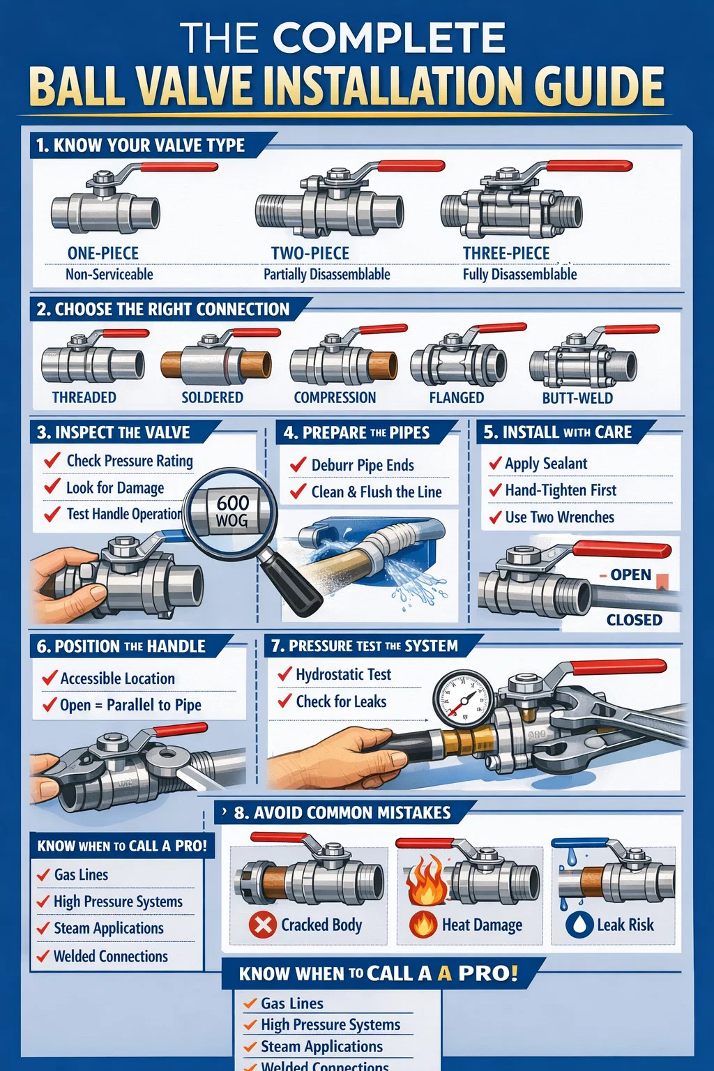
The three most common body styles are one-piece, two-piece, and three-piece ball valves. A one-piece ball valve is a compact, non-serviceable unit — once it fails internally, the whole valve is replaced. Installation is straightforward, but there is no way to disassemble it in the field. A two-piece valve can be partially disassembled and is the most widely used type in residential and light commercial plumbing. A three-piece ball valve allows full in-line disassembly without removing the valve body from the piping — critical for industrial systems where downtime is expensive.
Choosing the wrong body style for the application is itself an installation error. Installing a non-serviceable one-piece valve on a system that requires periodic maintenance creates unnecessary future labor.
Ball valves are available with threaded (NPT or BSP), soldered (sweat), compression, push-fit, flanged, and butt-weld ends. Each requires a completely different installation method:
Standard PTFE seats handle temperatures up to approximately 200°C (392°F) and are suitable for most water, gas, and mild chemical applications. For higher temperatures or aggressive media, reinforced PTFE, PEEK, or metal seats are required. Installing a standard PTFE-seated valve in a steam line or a high-temperature oil system is a common and costly mistake — the seats deform, the valve leaks, and it fails long before its rated service life.
A significant percentage of ball valve failures trace back to problems that existed — or were introduced — before the valve ever went into service. Pre-installation inspection takes ten minutes and can prevent a failed system test or an early field failure.
The pipe ends being connected to the ball valve must be clean, square-cut, and properly prepared for the connection type. Burrs on cut pipe ends are a common cause of seat damage — when the valve is first operated, the burr scores the ball surface and destroys the seal. Deburr all cut pipe ends, and flush any loose scale, weld spatter, or debris from the line before installing the valve.
For threaded connections, inspect the pipe threads with a thread gauge if available, or visually check for damaged, cross-threaded, or incomplete threads. A pipe thread that does not engage properly will never seal reliably regardless of how much sealant is applied.
Threaded ball valves are the most commonly installed type in residential, commercial, and light industrial settings. The following sequence applies to standard NPT (National Pipe Thread) connections.
| Valve Size | Material | Approx. Tightening Torque (ft-lb) | Turns from Hand-Tight |
|---|---|---|---|
| ½" | Brass | 35–45 | 1.5–2 |
| ¾" | Brass | 45–55 | 1.5–2 |
| 1" | Brass | 55–70 | 1.5–2 |
| 1½" | Stainless Steel | 70–90 | 1.5–2 |
| 2" | Stainless Steel | 90–120 | 1.5–2 |
Soldering a ball valve into a copper line is a standard plumbing task, but the heat required to make a proper solder joint is also capable of destroying the valve's internal seals if the process is not handled correctly. PTFE seats begin to deform at around 260°C (500°F), and a plumbing torch can easily exceed that at the valve body if the heat is applied carelessly.
Some installers wrap the valve body with a wet rag during soldering to act as a heat sink. This is a legitimate technique, particularly for tight spaces where heat cannot be directed as precisely as needed. Replace the wet rag as it dries — a dry rag provides no protection and becomes a fire hazard.
Most standard full-port ball valves are bidirectional — flow can enter from either end. However, orientation still matters for several practical and safety reasons.
The handle must be in a position where it can be operated quickly and without ambiguity — particularly for emergency shutoff valves. A handle that requires a contorted reach, or that operates in a direction that could be confused with adjacent equipment, is a safety hazard. Industry best practice is to orient the handle so that the open position is parallel to the pipe (flow direction) and the closed position is perpendicular to it — this is the universal convention for ball valves.
Ball valves can be installed in any orientation — horizontal, vertical (flow up or flow down), or at any angle. Unlike gate valves or check valves, there is no gravity-dependent seating mechanism that requires a specific attitude. However, on vertical lines carrying slurries, particulates, or viscous fluids, debris can settle on the ball when the valve is in the open position, leading to seat scoring when the valve is subsequently closed. In these applications, specifying a valve with a drain port or a purging connection is recommended.
Unidirectional ball valves — including V-port valves, valves with integral check functions, and most severe-service trunnion-mounted valves — have a clearly marked flow direction arrow on the body. Installing these in reverse creates either immediate malfunction or a dangerous situation where the valve body is pressurized in a way it was not designed for. Always check the valve body for flow direction markings before installation.
Additionally, some ball valves have a body cavity that can trap fluid when the valve is closed. On pressurized systems, this trapped fluid can create a pressure buildup that exceeds the body rating — known as body cavity overpressure. Valves used in such applications should have a pressure-relieving seat design, and the installation orientation should consider which side will be the upstream (higher-pressure) side.
The general installation steps apply across system types, but each application has requirements that must be addressed specifically.
Ball valves are the preferred shutoff valve for natural gas and LPG installations because they provide a full-bore, low-resistance flow path and are extremely reliable in on/off service. For gas service:
In hydronic (hot water) heating systems, ball valves serve as zone isolation valves, boiler service valves, and balancing aids. The operating temperatures in these systems — typically 60–90°C (140–194°F) for standard systems and up to 120°C (248°F) for high-temperature systems — are within the rating of standard PTFE-seated ball valves, but the combination of elevated temperature and water treatment chemicals (inhibitors, biocides) can accelerate seat degradation over time.
Install drain/service valves at low points to allow system isolation and draining without disturbing the entire circuit. When installing ball valves on flexible connections to pumps or heat exchangers, use union-ended ball valves so the component can be removed without draining the whole system.
Chemical compatibility is the primary installation concern in process applications. The ball valve body material, seat material, stem packing, and handle material must all be compatible with the process media. A single incompatible material in the valve assembly can cause failure — for example, a stainless steel body valve with standard PTFE seats may be chemically acceptable, but if the handle is zinc-plated steel and the process area is exposed to chlorine, the handle will corrode rapidly.
In process lines where valve position must be verifiable remotely, install a position indicator or limit switch at the time of initial valve installation. Retrofitting these devices to installed valves in cramped process areas is significantly more difficult and expensive.
In irrigation systems, ball valves are used as zone shutoffs and main line isolation. The primary installation concern here is UV exposure and freeze protection. PVC-bodied ball valves should not be exposed to direct sunlight without UV-protective covering — UV degradation of PVC can halve the expected service life. In climates where freezing occurs, ball valves must be installed with drain capability or insulation. A ball valve left full of water in a frozen line will fail — the ice expansion exceeds the body strength of most valve materials.
When a ball valve is being installed with an electric, pneumatic, or hydraulic actuator, the installation involves additional steps beyond the valve-to-pipe connection.
Most actuated ball valves use an ISO 5211 standard mounting pad, which provides a common interface between valve stems and actuators from different manufacturers. Before mounting the actuator, verify that the stem drive (square, double-D, or round with keyway) matches the actuator's drive coupling. A mismatch that appears to fit initially will strip under torque.
Set the actuator's end-of-travel stops before connecting to the pipeline. Over-travel in either direction can damage the valve seats — most ball valves tolerate no more than 1–2 degrees of over-rotation beyond the fully open or fully closed position.
Spring-return pneumatic actuators and fail-safe electric actuators move to a predetermined position on loss of power or air supply. The fail-safe position must be determined before installation, not after — it affects actuator selection, spring orientation, and wiring. A valve that fails open in a fuel supply line or fails closed on a cooling water line can have serious consequences. Document the fail-safe position on the installation record.
Electric actuators require proper conduit or cable entry installation to maintain the actuator's ingress protection rating. An IP67-rated actuator wired with an unsealed cable entry provides no better protection than an unrated one. Use the correct cable glands, apply appropriate thread sealant to conduit connections, and verify the electrical supply voltage matches the actuator nameplate rating before energizing.
No ball valve installation is complete until it has been tested. The type of test depends on the application, but the principle is the same: verify the connections are leak-free and the valve operates correctly under conditions representative of service.
Hydrostatic testing uses water (an incompressible fluid) to pressurize the system above its normal operating pressure. The standard test pressure for most systems is 1.5 times the maximum allowable operating pressure (MAOP), held for a minimum of 30 minutes. During this period, inspect all connections — including the packing gland at the valve stem — for any weeping or dripping. A small amount of moisture that dries without return is not necessarily a leak; a drop that reforms is.
Test the valve's shut-off capability by closing it during the pressurized test and verifying that there is no flow past the closed ball. This tests both the seats and the ball sealing surface.
Gas systems are typically tested with nitrogen (not air, which contains moisture and oxygen) or with the actual service gas at low pressure before full system commissioning. Apply the test medium, isolate the system, and monitor pressure for a defined period — many gas codes require a hold of 10 minutes at 1.5× MAOP with no measurable pressure drop. Apply leak detection solution to all joints including the valve body-to-end connection joints, the stem packing area, and the body cavity vent if present.
After pressure testing, cycle the ball valve through its full range of motion — open to close and back to open — at least three times while the system is under pressure. This confirms that the valve operates without excessive resistance, that the handle returns to the correct positions with clear tactile stops, and that no leaks develop at the stem packing during operation. Leaks that appear only during valve operation, not during static pressure hold, indicate stem packing or stem seal problems.
The following table summarizes the most frequently observed installation errors, their consequences, and the corrective action.
| Installation Mistake | Likely Consequence | Prevention |
|---|---|---|
| Over-tightening threaded connections | Cracked valve body, damaged seats | Use a torque wrench; follow manufacturer specs |
| Applying heat directly to valve body during soldering | Deformed PTFE seats, immediate leak | Heat the pipe, not the body; use wet rag as heat sink |
| Installing in a closed position during soldering | Seat damage from conductive heat | Always open the valve fully before soldering |
| Not deburring cut pipe ends | Ball surface scoring, seat leakage | Deburr all pipe ends before valve installation |
| Skipping the pressure test | Undetected leaks discovered during operation | Always test before returning the system to service |
| Wrong valve type for service media | Premature seat failure, contamination, safety hazard | Verify chemical and temperature compatibility before ordering |
| Handle inaccessible after installation | Inability to operate valve in an emergency | Plan handle orientation before final tightening |
| Using PTFE tape on gas lines where code requires dope | Code violation, potential gas leak | Check local gas code before installation |
A ball valve that is correctly installed on day one can still become a maintenance problem if the installation does not account for future service access. This is particularly relevant in concealed locations — behind walls, above ceilings, or under floors — and in process plant environments where equipment is packed tightly.
Any ball valve installed in a concealed location should be provided with an access panel that allows the valve to be operated and inspected without destructive access. The access panel should be large enough to accommodate tools — not just a hand — since a valve that has seized due to years of inactivity may require significant force to operate, and that force cannot be applied safely through a restricted opening.
For ball valves in process plant environments, maintain a minimum of 150mm (6 inches) clear space around the handle or actuator on all sides. This allows a technician to apply a wrench extension if needed, and provides room for a portable leak detector or thermographic camera during inspection.
Every installed ball valve should receive a tag or label indicating its tag number, the system it serves, its normal operating position (normally open or normally closed), and the date of installation. This is not optional bureaucracy — it is a safety and maintenance requirement. A facility with hundreds of unlabeled valves is a facility where isolation errors occur. Isolation errors cause process upsets, injuries, and fatalities.
Create or update the system's valve register at the time of installation. The register should record the valve's tag number, manufacturer, model, size, pressure and temperature rating, seat and body material, date of installation, and location. This information is required for future maintenance planning and for any future system modifications.
Ball valves that remain in one position for extended periods — particularly in water systems with high mineral content — can develop stiction where the ball effectively bonds to the seats. A valve that has not been operated in two or three years may require significantly more torque to move than a new valve. Schedule a routine exercise of all ball valves that are not operated in normal system operation — at minimum once per year, or quarterly for critical isolation valves. During each exercise, check for any leakage at the stem packing and verify that the valve reaches full open and full closed positions without abnormal resistance.
Many ball valve installations are straightforward and can be completed by a competent maintenance technician or experienced DIY homeowner. However, certain installations require a licensed professional, and recognizing those boundaries is itself part of correct installation practice.
For standard residential plumbing — replacing a shutoff under a sink, adding an isolation valve to a water heater, or installing a garden hose ball valve — a confident homeowner with the right tools can do the work correctly by following the steps in this guide. The key is matching the task to the installer's actual competence and the system's actual risk level.
Recommended Products
Copyright © Yancheng Yanye Hydraulic Parts Co., Ltd. All Rights Reserved
Custom Ball Valve Factory
China Ball Valve Manufacturers
![]()


 English
  русский
  Español


 KHP-10 KHP-16 KHP-20 KHP-25 KHP-32")


