
2026-03-23
Content
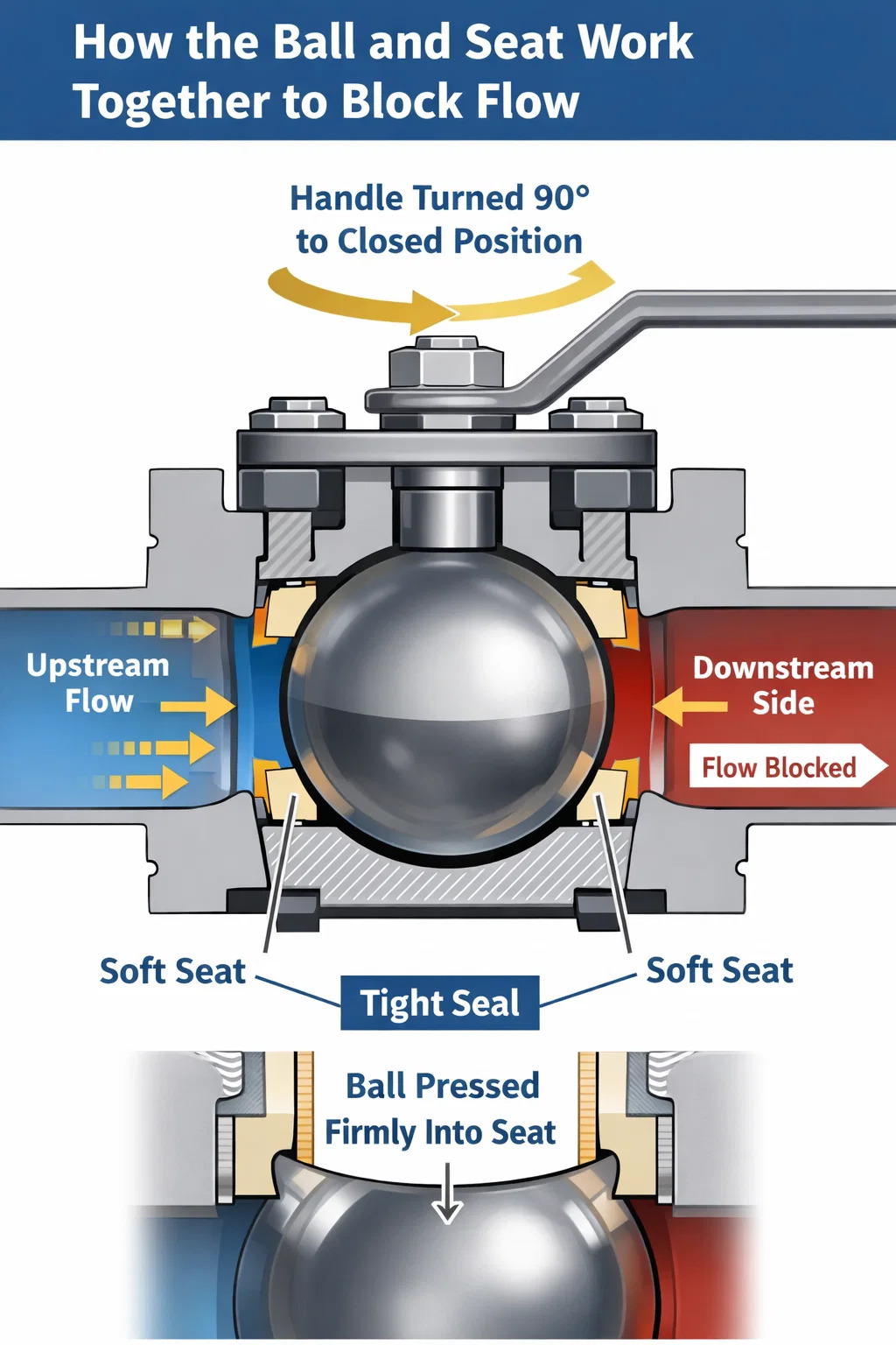
A ball valve does not leak because it achieves a tight, zero-clearance seal between a precision-machined spherical ball and two soft seats pressed against both sides of that ball. When the handle is turned 90 degrees to the closed position, the solid portion of the ball blocks the flow path completely, while the upstream line pressure actually pushes the ball harder into the downstream seat — a self-energizing effect that makes the seal tighter the more pressure there is. Under correct installation and proper maintenance conditions, a high-quality ball valve can hold bubble-tight shutoff at pressures up to 1,000 psi or more, with essentially zero leakage measured even by sensitive gas-detection instruments.
That said, no valve lasts forever without attention. The sections below explain exactly how the internal sealing mechanism works, what materials are involved, how different ball valve designs handle extreme conditions, and what causes the seal to eventually fail — so you can choose the right valve and keep it performing reliably for years.
The core of any ball valve is a sphere — typically made from stainless steel, brass, or chrome-plated carbon steel — with a precisely bored hole called a port running through its center. In the open position, this port aligns with the pipeline, allowing fluid to pass straight through. Rotating the stem 90 degrees turns the solid wall of the sphere into the flow path, physically blocking any passage.
Surrounding the ball on both the upstream and downstream sides are valve seats — rings made from materials like PTFE (polytetrafluoroethylene), PEEK (polyetheretherketone), or reinforced nylon. These seats are machined to match the ball's curvature within very tight tolerances, typically ±0.001 to ±0.005 inches depending on the pressure class. The seats are held under slight spring or mechanical preload so that even before system pressure is applied, the ball is already in contact with the seat material around its entire circumference.
When the valve is shut and line pressure builds upstream, that pressure acts on the projected area of the ball and pushes it firmly against the downstream seat. The soft seat material — PTFE is by far the most common — conforms microscopically to any surface irregularities on the ball, filling gaps that rigid metal-to-metal contact would leave open. The result is what the industry calls a Class VI shutoff, which under ANSI/FCI 70-2 standards allows a maximum of only 0.0005 ml per minute per inch of seat diameter at the rated differential pressure — for practical purposes, zero leakage.
There are two fundamental designs that handle the pressure-sealing differently:
Both designs achieve the same end result — a leak-free seal — but through slightly different mechanical paths. Choosing the wrong design for the pressure range is one of the most common reasons a ball valve leaks prematurely.
The seat material is the single most important variable in determining whether a ball valve holds a leak-free seal across its full service life. Each material has a distinct combination of chemical compatibility, temperature range, and mechanical compliance.
| Seat Material | Temperature Range | Best For | Limitation |
|---|---|---|---|
| Virgin PTFE | -40°F to 400°F (-40°C to 204°C) | General service, water, oil, gases | Cold-flows under sustained high load |
| Filled PTFE (glass/carbon) | -40°F to 450°F (-40°C to 232°C) | Higher-pressure, abrasive media | Less chemically universal than virgin PTFE |
| PEEK | Up to 500°F (260°C) | Steam, high-temp hydrocarbons | Higher cost, stiffer — needs precise ball finish |
| Metal (Stellite, Inconel) | Up to 1,500°F (815°C) | Cryogenic, high-temp, abrasive slurries | Not bubble-tight; allows micro-leakage by Class IV standard |
| Nylon (PA) | Up to 200°F (93°C) | Low-cost water and air service | Absorbs moisture, loses dimensional stability |
PTFE dominates the market because it offers near-universal chemical resistance (it is attacked only by molten alkali metals and free fluorine), and its low friction allows the ball to rotate without scoring the seat surface. However, PTFE "cold-flows" — under sustained compressive load it slowly deforms. In applications where the valve stays closed for months at high pressure, this can eventually reduce the contact force and introduce a small leak path. Filled PTFE or PEEK seats significantly reduce this phenomenon.
Metal seats sacrifice the bubble-tight shutoff of soft seats in exchange for the ability to handle extreme temperatures and abrasive particles. A metal-seated ball valve operating at, say, 1,200°F in a catalyst process can still deliver consistent, repeatable shutoff over thousands of cycles — just not to the same leakage standard as a soft-seated valve at ambient temperature.
The port seal is only half the picture. A ball valve also has to prevent process fluid from escaping around the stem — the shaft that connects the ball to the external handle or actuator. This is called fugitive emission control, and in industries like oil and gas, petrochemical, and pharmaceuticals, regulatory limits are strict. The EPA's Method 21 protocol, for example, requires that valve stem leakage not exceed 500 ppm of volatile organic compounds (VOCs).
Stem sealing is typically accomplished with one or more of the following:
High-integrity applications such as LNG terminals and semiconductor fab lines often specify ball valves with double-block-and-bleed (DBB) configurations that include not just redundant stem seals but also bleed valves that allow the cavity between the two seats to be vented and verified as leak-free before the downstream side is opened to the process.
No soft seat can compensate for a rough ball surface. The ball must be ground and polished to a surface finish typically specified as Ra 0.4 μm (16 μin) or better for general industrial service, and Ra 0.2 μm or better for critical applications. At that level of smoothness, even a relatively hard material like PEEK can form a conformal seal with the ball.
The ball surface also receives protective coatings in demanding services:
A scored or pitted ball surface is the most common cause of a ball valve that used to seal well but now leaks in the closed position. Even microscopic scratches — caused by sand, pipe scale, weld spatter, or operating under cavitating conditions — create leak paths that no soft seat can bridge.
Ball valves have largely displaced gate valves and globe valves in new installations for isolation service, and the reason is directly related to sealing reliability. Consider how the competing designs work:
Studies comparing valve types in refinery service have shown that ball valves achieve 60 to 80% lower maintenance costs over a 10-year period compared to gate valves performing equivalent isolation duties, largely because they hold their shutoff performance through far more open-close cycles without repacking or resurfacing.
Even a well-designed ball valve will eventually develop leakage if it is misapplied or neglected. The failure modes fall into distinct categories:
PTFE seats cold-flow, as described above. They also degrade when exposed to media outside their chemical compatibility envelope — concentrated sulfuric acid above 150°F, for instance, attacks PTFE. When seats lose their dimensional integrity, they no longer maintain full contact with the ball in the closed position. The fix is seat replacement, which in most floating-ball designs requires only removing the end connections and pressing out the old seats — a field-serviceable operation taking under an hour for a trained technician.
Sand, weld slag, pipe scale, and other solids in the flow stream scratch the ball surface during operation. Even 5–10 microns of surface damage at the seat contact zone can break the Class VI shutoff. Prevention measures include upstream strainers (typically 40–80 mesh for general service), ensuring all pipe sections are cleaned and flushed before valve installation, and specifying hardened ball coatings — tungsten carbide or hard chrome — where particulate contamination is expected.
Stem leakage (fugitive emission) increases gradually as packing material compresses and extrudes over time under thermal cycling. On valves without live-loading, simply retightening the packing gland nut by one-quarter to one-half turn typically restores the seal. Over-tightening is counterproductive — it increases operating torque and accelerates stem wear without proportionately improving the seal. On automated valves, increased actuator torque consumption is often the first measurable sign of packing degradation.
Ball valves installed in liquid service outdoors are vulnerable to freeze damage if the cavity between the ball and seats retains liquid that expands on freezing. The cavity pressure during ice formation can exceed 40,000 psi — far beyond the structural rating of any standard valve — cracking the body or deforming the seats. Prevention options include cavity relief holes (drilling a small hole in the ball so the cavity is always at upstream pressure), full-bore designs that minimize trapped volume, and heat tracing where freezing is anticipated.
Flanged ball valves have a specific bolt torque sequence and torque value specified by the manufacturer. Under-torquing the flange bolts leaves the gasket insufficiently compressed, producing a body-to-flange leak that looks like internal seat leakage until inspected closely. Over-torquing on plastic-bodied valves distorts the body, which shifts the ball off-center relative to the seats and immediately compromises shutoff. Always follow the torque table in the valve's installation manual — values typically range from 25 ft-lbs for 1" ANSI 150 flanges to over 500 ft-lbs for 12" ANSI 600 flanges.
In hydrocarbon and chemical processes, regulations including API 607 and ISO 10497 require that ball valves maintain acceptable shutoff even after a fire has damaged their soft seats. A standard PTFE seat melts around 620°F (327°C). In a fire scenario, this would normally destroy the seat's sealing capability and allow the process fluid to escape, fueling the fire further.
Fire-safe ball valves solve this with a metal-to-metal secondary seat behind the primary soft seat. Once the soft seat burns away, the metal backup comes into contact with the ball, providing a reduced but still functional barrier. The standard tests per API 607 subject the assembled valve to direct flame at 1,400°F (760°C) for 30 minutes and then require it to hold external leakage below 1.0 ml/min per inch of nominal pipe diameter at 1.1 times the rated pressure. Meeting this test requires meticulous design of the spring loading that brings the metal backup seat into contact.
Anti-static features — a conductive spring or graphite insert connecting ball to stem to body — are specified alongside fire-safe designs. Without them, the non-conductive PTFE seat can allow electrostatic charge to build up on the ball during flow, eventually discharging as a spark that ignites flammable vapors in the valve cavity. Anti-static paths maintain electrical continuity below 10 ohms resistance throughout the valve's operating life per API 608 requirements.
Ball valves are available in two bore configurations:
From a pure sealing standpoint, both configurations achieve Class VI shutoff when properly built. The choice between them is driven by pressure drop requirements, pigging requirements, and cost — not by inherent sealing capability. Full-bore valves cost roughly 15 to 30% more than reduced-bore equivalents in the same material and pressure class.
No matter how well a valve is built, verifying the seal is essential before a system goes into service. The two primary test methods are:
For in-service verification without disassembly, ultrasonic leak detectors can identify the turbulent sound signature of a leaking valve seat through the valve body wall. This non-invasive technique can detect leaks as small as 0.5 SCFH (standard cubic feet per hour) in gas service without requiring process shutdown — a significant advantage for continuous production facilities.
Ball valves should not be used for throttling. Operating a ball valve in a partially open position exposes the seat to high-velocity flow across the sealing surface, causing erosive damage within a short period. If you leave a ball valve partially open for extended periods, the sealing zone of the ball will be eroded and the valve will lose its ability to shut off cleanly. For throttling service, use a globe valve, needle valve, or butterfly valve with an appropriate trim design.
Under clean service conditions with compatible media, PTFE seats typically maintain Class VI shutoff for 50,000 to 100,000 full open-close cycles. In calendar terms, a valve that cycles ten times per day in clean service would have a seat life of 14–27 years before needing repacking. Abrasive or chemically aggressive media, high cycle rates, or operating above the seat's temperature limit all reduce service life significantly.
For threaded or socket-weld valves in small sizes (½" to 2"), replacement is almost always more economical than repair — new valve cost is often less than the labor cost for disassembly, seat sourcing, and reassembly. For larger flanged ball valves (4" and above) or special alloy construction (Hastelloy, titanium, Duplex SS), repair via seat and seal kits is standard practice because the ball and body represent most of the valve's value and are rarely damaged in isolation.
In floating-ball designs, yes — the sealing direction matters. The upstream pressure pushes the ball against the downstream seat, creating the primary seal. Reversing flow direction in a single-seat-loaded valve can in some designs reduce the seating force and allow minor leakage. Most modern floating-ball valves are designed for bidirectional sealing, with seats on both sides and appropriate spring loading, but the manufacturer's specification should always be confirmed. Trunnion-mounted valves are inherently bidirectional because the seating force is generated independently of flow direction by spring-loaded seats.
These classifications under ANSI/FCI 70-2 define the maximum allowable leakage rate at rated pressure. Class IV (metal-seated valves) allows up to 0.01% of the valve's rated Cv flow capacity. Class V tightens this to 0.0005 ml per minute per inch of seat diameter per psi of differential pressure. Class VI — the standard for soft-seated ball valves — specifies a fixed maximum in ml per minute based purely on valve size, and is the tightest widely used classification. A 4" Class VI valve, for example, is limited to 1.0 ml/min of leakage under test conditions.
Recommended Products
Copyright © Yancheng Yanye Hydraulic Parts Co., Ltd. All Rights Reserved
Custom Ball Valve Factory
China Ball Valve Manufacturers
![]()


 English
  русский
  Español


")

 KHP-10 KHP-16 KHP-20 KHP-25 KHP-32")
