2026-07-13
Content
There are nine flow valve types used across piping systems today: gate, globe, ball, butterfly, check, plug, needle, diaphragm, and pinch valves. Each one controls flow through a different mechanical action — a wedge that drops into place, a disc that rotates ninety degrees, a ball that turns to open a bore, or a flexible sleeve that squeezes shut. The valve type you need depends on three things: whether you need on/off shutoff or fine throttling, what the fluid is doing to the internals (abrasive slurry, corrosive chemical, clean water, compressed air), and how much pressure drop the system can tolerate.
Ball and gate valves dominate isolation duty because they create almost no obstruction when fully open. Globe and needle valves dominate throttling duty because their internal geometry is built for partial-open flow control without chattering or excessive wear. Check valves are the odd ones out — they never touch flow control at all, they only stop reverse flow. The rest of this guide breaks down each type, how to size and select between them, and where each one earns its place in a real piping layout.
Every flow valve works by changing the size or shape of the opening a fluid passes through. The mechanism used to do that splits valves into two broad motion families, and understanding this split makes the rest of valve selection much easier.
Gate, globe, diaphragm, and pinch valves move a closure element in a straight line, perpendicular or parallel to the flow path. A gate drops down through the flow bore. A globe disc moves up and down against a seat. This straight-line motion tends to require more turns of a handwheel to fully open or close, but it gives finer control over the flow curve, which is why globe valves show up wherever a plant needs to throttle steam or hot water precisely.
Ball, butterfly, and plug valves rotate a closure element, typically through a quarter turn (90 degrees), between fully open and fully closed. This is mechanically simpler, faster to operate, and easier to automate with a quarter-turn actuator. The tradeoff is that most rotary valves are not built for fine throttling near the closed position — the ball or disc edge sits close to the seat and erosion accelerates quickly if used for continuous partial-open service.
A third concept worth knowing is the flow characteristic curve, which describes how much flow change you get per degree of valve travel. Linear characteristic valves increase flow evenly with travel. Equal-percentage valves increase flow slowly at first, then rapidly near full open, which suits systems where pressure drop varies a lot across the operating range. Quick-opening valves reach near-maximum flow within the first small percentage of travel, which is exactly what you want in an on/off shutoff valve and exactly what you do not want in a control valve.
The table below lines up the most widely used valve types by primary function, typical size range, and where each one falls short. Use it as a quick filter before reading the detailed sections that follow.
| Valve Type | Primary Function | Typical Size Range | Main Limitation |
|---|---|---|---|
| Gate | Full on/off isolation | 1/2 in to 96 in | Poor throttling, slow to operate |
| Globe | Precise throttling | 1/4 in to 24 in | High pressure drop even when open |
| Ball | Quick on/off shutoff | 1/4 in to 48 in | Limited throttling life in standard ports |
| Butterfly | Large-diameter flow control | 2 in to 144 in | Disc obstructs flow even when open |
| Check | Backflow prevention only | 1/4 in to 72 in | No manual flow adjustment |
| Plug | On/off with tight sealing | 1/2 in to 24 in | Higher operating torque |
| Needle | Fine, low-flow metering | 1/8 in to 2 in | Not suited to high flow volumes |
| Diaphragm | Corrosive or slurry isolation | 1/4 in to 12 in | Pressure and temperature ceilings |
| Pinch | Slurry and abrasive media flow | 1/2 in to 24 in | Sleeve wear in high-cycle service |
A gate valve works by dropping a wedge-shaped or parallel-slide gate straight down across the flow path. When it retracts fully, the bore is essentially unobstructed, so a fully open gate valve produces almost no pressure loss — a genuine advantage in long transmission pipelines where every bit of head loss adds pumping cost. The tradeoff shows up the moment the gate sits partway open: turbulent flow around the partially exposed gate edge causes vibration, seat wear, and eventually leakage, so gate valves are built and specified strictly for full-open or full-closed use, never for throttling.
Operation typically needs multiple handwheel turns, which makes gate valves slow to close in an emergency compared with a quarter-turn ball or butterfly valve. Two common gate designs exist: rising stem gates, where the stem visibly rises as the valve opens, giving an instant visual indication of position, and non-rising stem gates, used where vertical clearance is limited, such as underground water mains.
Globe valves get their name from the spherical body shape that houses an S-shaped internal flow path. That path forces the fluid to change direction twice as it moves through the valve, which is precisely what makes globe valves so good at throttling — the disc-and-seat arrangement sits directly in the flow stream at every position, giving smooth, controllable flow reduction from fully open down to a trickle. The same S-path is also why globe valves carry a noticeably higher permanent pressure drop than a gate or ball valve of the same size, even wide open.
Because the disc travels a short linear distance to fully seat, globe valves close faster and more precisely than gate valves, and they hold up far better under frequent cycling. This makes them the standard choice for steam control stations, boiler feedwater regulation, and any application where an operator needs to dial in an exact flow rate rather than simply switch flow on or off.
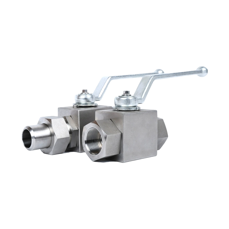
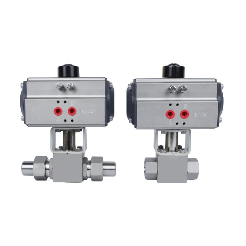
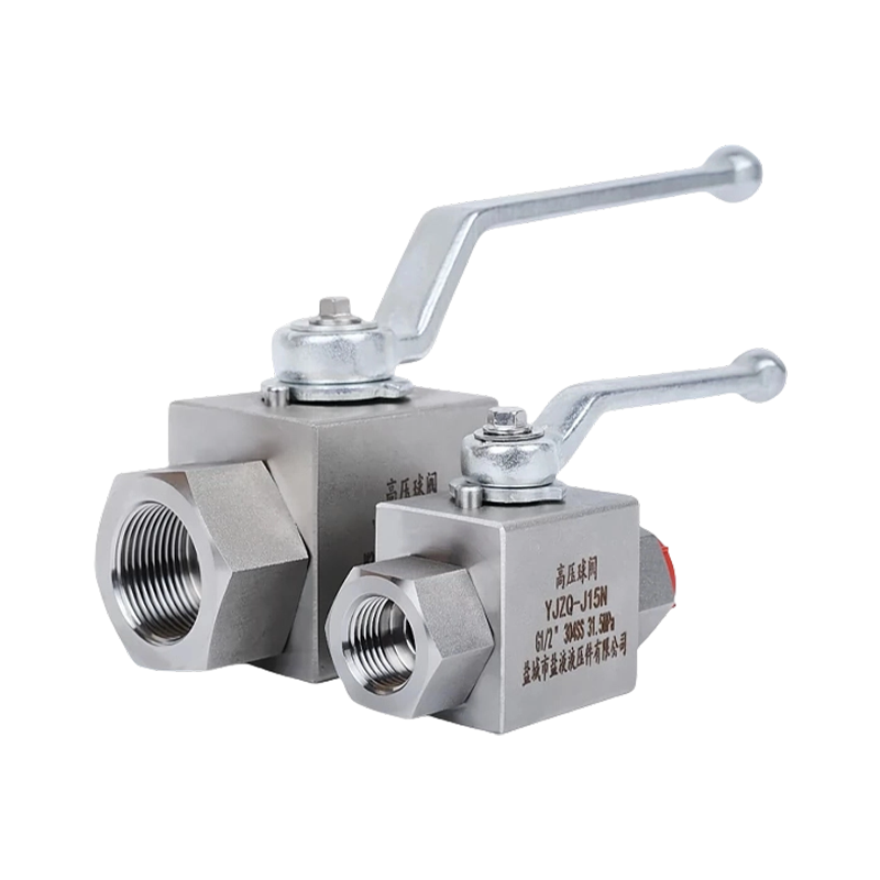
A ball valve uses a bored sphere that rotates a quarter turn inside the body. Align the bore with the pipe and flow passes almost unrestricted; rotate ninety degrees and the solid face of the ball blocks flow completely. That quarter-turn action means a ball valve can go from fully open to fully closed in about one second on a standard lever handle, which is why ball valves are the default choice anywhere fast emergency shutoff matters, from gas distribution lines to instrumentation air supply.
Standard-port (reduced-bore) ball valves are common and cost less, but full-port ball valves — where the bore matches the pipe's internal diameter exactly — are specified whenever pigging, minimal pressure drop, or slurry flow is involved. Ball valves seal extremely tightly against both liquids and gases thanks to resilient seat materials like PTFE, but that same soft seat becomes the weak point in high-temperature steam service, where a metal-seated ball valve is used instead.
A butterfly valve mounts a flat or contoured disc on a central shaft that rotates within the pipe bore. Unlike a ball valve, the disc never fully retracts — even fully open, the disc's thin edge remains in the flow path, which produces a small but real pressure drop compared with a ball or gate valve. What butterfly valves give up in zero-obstruction flow, they make up in weight and cost at large diameters: a 24-inch butterfly valve weighs a fraction of an equivalent gate valve and installs in a much shorter face-to-face length, since most designs mount as a thin wafer or lug pattern between two pipe flanges rather than bolting on with its own flanged ends.
Butterfly valves come in two structural families. Concentric designs use a rubber-lined seat and are economical for low-pressure water and air service. Triple-offset designs use a metal seat with three geometric offsets that let the disc rotate without rubbing the seat until the final degrees of closure, giving bubble-tight shutoff at high pressure and temperature without relying on a soft seat.
A check valve never needs a handwheel, lever, or actuator because it opens and closes on its own in response to the direction of flow. Forward flow pushes a disc, ball, or flap open; any reversal in flow direction pushes the same element back onto its seat and stops backflow immediately. This makes check valves essential wherever a pump could siphon back, a compressor could stall and reverse, or two flow sources could otherwise cross-contaminate each other.
Three designs cover most applications. Swing check valves use a hinged disc that swings open with flow and swings shut under gravity and backpressure — simple and low-restriction, but prone to a hard slam in systems with sudden flow reversal. Lift check valves use a disc that lifts straight up off its seat, similar internally to a globe valve, and handle higher pressure systems well. Dual-plate (wafer) check valves use two spring-loaded half-discs that close faster than a swing check, reducing the water-hammer slam that damages pipework in high-velocity systems.
Beyond the six workhorse types above, four specialty valve designs solve problems the mainstream types cannot handle well.
A needle valve uses a slender, tapered stem that threads into a matching seat, giving extremely fine control over very small flow volumes. The long, gradual taper means many turns of the stem produce only a small change in flow area, which is exactly the resolution needed for calibrating instrumentation, metering pilot gas lines, or bleeding small volumes from a pressurized system. Needle valves are rarely built above 2-inch nominal size because their entire design purpose is precision at low flow, not volume.
A plug valve rotates a tapered or cylindrical plug with a bored passage through it, similar in concept to a ball valve but with a plug shape instead of a sphere. Plug valves seal reliably against abrasive and dirty media because the flat sealing surfaces resist the scoring that a spherical ball surface can suffer, and multi-port plug valve bodies can direct flow between three or four pipe connections from a single valve, which reduces the piping needed for flow-diversion applications in chemical batching systems.
A diaphragm valve uses a flexible membrane, usually rubber or PTFE-lined, that is pressed down onto a weir or straight-through seat to stop flow. Because the diaphragm is the only wetted part exposed to the fluid, and the valve body itself never contacts the media, diaphragm valves excel with highly corrosive chemicals, slurries, and sterile or ultra-pure fluid systems where any metal contact would contaminate the product. Their limitation is largely thermal — the elastomer diaphragm material sets both the pressure and temperature ceiling for the valve.
A pinch valve uses a flexible rubber sleeve that is mechanically or pneumatically squeezed shut across its full diameter. Because there are no internal metal parts anywhere in the flow path, pinch valves handle abrasive slurries, mining tailings, and fibrous or high-solids-content fluids that would rapidly erode a ball or gate valve's internal surfaces. The sleeve is the wear item and needs periodic replacement, which is the main tradeoff for the abrasion resistance it provides.
Valve selection almost always comes down to answering five questions in order. Skipping any one of them is the most common reason a valve gets specified wrong and fails early.
The valve type determines the mechanism, but the material determines whether that mechanism survives the service conditions. Body and trim material choice generally follows the fluid chemistry and temperature far more than it follows the valve type itself.
| Material | Common Use | Notes |
|---|---|---|
| Bronze / brass | Potable water, low-pressure air | Cost-effective, moderate corrosion resistance |
| Cast iron / ductile iron | Water distribution, fire protection | Strong and economical at larger diameters |
| Carbon steel | Oil, gas, general industrial process | Good strength-to-cost ratio, moderate corrosion resistance |
| Stainless steel | Chemical processing, food and beverage | Strong corrosion and temperature resistance |
| PVC / CPVC | Corrosive chemicals, irrigation | Lightweight, limited temperature ceiling |
| PTFE-lined | Highly corrosive acids and solvents | Excellent chemical resistance, higher cost |
Most flow valve failures trace back to one of a small number of root causes, and recognizing the pattern early usually prevents a full valve replacement.
A basic preventive routine — cycling isolation valves periodically so they do not seize in one position, inspecting packing glands on a schedule, and tracking cycle counts on check and control valves — catches the majority of these failure modes before they cause unplanned downtime.

Real piping systems rarely use just one valve type; most process lines mix several types by function.
Gate valves dominate main isolation points along transmission lines because of their low pressure loss when open. Butterfly valves handle large-diameter distribution branches where weight and installed cost matter. Check valves sit downstream of every pump to stop backflow into the wet well.
Ball valves handle most manual isolation duty because of fast, tight shutoff. Globe valves appear at control points needing precise throttling of process fluid. Plug and diaphragm valves take over wherever the media is abrasive slurry or aggressive chemical.
Ball valves isolate zone circuits for maintenance. Globe and needle-style balancing valves fine-tune flow rate across a building's hydronic loops so distant zones receive adequate heating or cooling water.
Diaphragm and sanitary ball valves dominate because their smooth, cleanable internal surfaces meet hygienic processing requirements and avoid product contact with non-wetted parts.
Ball valves and gate valves are the two most widely installed flow valve types across general industry, because most piping systems need simple on/off isolation far more often than continuous throttling.
A standard ball valve can be partially opened for rough flow adjustment, but the ball edge sits close to the seat at partial travel and wears quickly under continuous throttling. A globe or needle valve is the correct choice for regular flow regulation.
The S-shaped internal flow path in a globe valve forces the fluid to change direction twice, which is what enables precise throttling but also causes a permanently higher pressure loss than a gate valve's straight-through bore.
A check valve operates automatically based on flow direction and has no manual control — it only prevents backflow. A control valve, typically a globe or ball design paired with an actuator, is adjusted deliberately to regulate flow rate or pressure.
Pinch valves and diaphragm valves handle abrasive slurry best because neither design has rigid metal parts sitting directly in the flow path, which avoids the rapid erosion that a ball or gate valve would suffer in the same service.
Valve size is generally matched to the pipe's nominal diameter, then adjusted based on the required flow coefficient (Cv) for the expected flow rate and acceptable pressure drop, rather than sized independently of the pipe.
Recommended Products
Copyright © Yancheng Yanye Hydraulic Parts Co., Ltd. All Rights Reserved
Custom Ball Valve Factory
China Ball Valve Manufacturers




 English
  русский
  Español