2026-06-15
Content
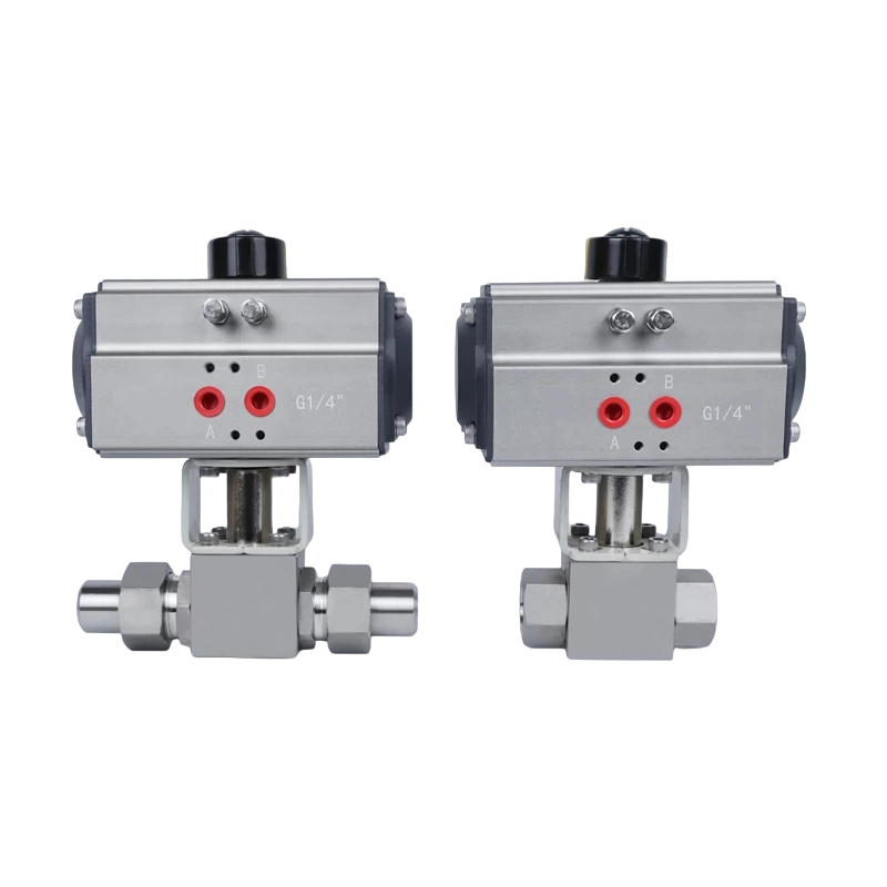
A pneumatic actuator ball valve combines a quarter-turn ball valve body with a compressed-air-driven actuator to open or close a pipeline automatically — no manual handwheel, no electric motor required. The actuator converts air pressure (typically 40–120 PSI / 2.8–8.3 bar) into rotary torque that turns the ball 90 degrees, either allowing full flow or achieving a complete shutoff with near-zero leak rate. This pairing is the go-to solution across oil and gas, chemical processing, water treatment, food and beverage, and pharmaceutical plants because it offers fast actuation speed (often 0.5–3 seconds for a full stroke), reliable fail-safe behavior, and compatibility with hazardous-area classification where electric actuators present ignition risks.
Unlike gate valves or globe valves that require multiple turns to operate, a ball valve reaches its fully open or fully closed position with a single 90-degree rotation. Paired with a pneumatic actuator, this quarter-turn characteristic translates directly into rapid, repeatable cycling — a crucial advantage on automated production lines or emergency shutdown (ESD) systems where response time is measured in fractions of a second. Industry surveys consistently show that over 60% of automated isolation valves installed in new process plants worldwide are pneumatically actuated ball valves (source: Valve World Americas, 2022 market report).
The core takeaway: if you need fast, repeatable, automated on/off or throttling control of liquids, gases, or slurries in a pipeline, a pneumatic actuator ball valve is almost certainly on the short list. The sections below unpack every dimension of this technology — how the internal components work together, how to size and select one correctly, what the common failure modes are, and how to extend service life through proper maintenance.
Understanding the assembly at a component level makes selection and troubleshooting far more straightforward. There are two distinct sub-systems — the valve body and the actuator — joined by a standardized mounting interface (commonly ISO 5211 flange pattern) and a stem/drive key connection.
The valve body houses a spherical ball with a precision-bored hole (the "bore" or "port") through its center. When the bore aligns with the pipeline axis, flow is unrestricted — this is the fully open position. Rotating the ball 90 degrees places the solid wall of the sphere across the flow path, creating a shutoff. The ball is held in contact with upstream and downstream seats (typically PTFE, RTFE, or metal-to-metal for high temperatures) that form the primary sealing surfaces. Seat material choice is one of the most critical decisions in ball valve specification because it dictates temperature range, chemical compatibility, and acceptable pressure differential.
Ball valves are available in two main bore configurations:
Body materials span carbon steel (A216 WCB), stainless steel (CF8M / 316), duplex stainless, Hastelloy, brass, and PVC/CPVC for corrosive or hygienic services. Pressure ratings follow ASME B16.34 classes — Class 150, 300, 600, 900, 1500, and 2500 — with working pressure limits rising steeply as class increases. A Class 150 stainless ball valve, for example, is rated to roughly 285 PSI at ambient temperature, while a Class 600 equivalent handles approximately 1,480 PSI under the same conditions.
The actuator converts compressed air energy into mechanical torque delivered to the ball valve stem. Two actuator mechanisms dominate the market:
Actuators are also classified by their fail-safe action:
Selection between spring return and double-acting depends on the process hazard analysis (PHA) and the defined fail-safe position: fail-open (FO), fail-closed (FC), or fail-in-last-position (FL). Emergency shutdown valves are almost always FC with spring-return actuators; process control isolation valves where loss of air pressure should not interrupt flow often use FO configurations.
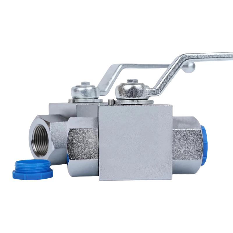
Selecting the right pneumatic actuator ball valve requires matching several interdependent parameters. A mismatch in any one of them can lead to premature seat wear, actuator stall, or unsafe operation.
| Parameter | Typical Range | Why It Matters |
|---|---|---|
| Supply Air Pressure | 40–120 PSI (2.8–8.3 bar) | Determines output torque; actuator must be sized at minimum available pressure |
| Required Torque (Valve) | Varies widely by size and seat material | Actuator output torque must exceed valve seat torque with a safety factor of 1.25–1.5x |
| Cv (Flow Coefficient) | Varies by size and bore type | Governs pressure drop and flow capacity at a given differential pressure |
| Temperature Range (Seat) | PTFE: -29 to 200°C; Metal: up to 500°C+ | Seat material must remain resilient across the full operating temperature range |
| Stroke Time | 0.5–30 seconds (adjustable via flow controls) | Affects water hammer risk; ESD valves need fast closure, process valves often need slow |
| Cycle Life | 100,000–1,000,000+ cycles | Critical for high-frequency cycling in packaging or water treatment applications |
| Leakage Class (Seat) | ANSI/FCI 70-2 Class IV to Class VI | Soft-seat ball valves achieve Class VI (bubble-tight); metal seats typically Class IV–V |
The required valve torque is not a single static number — it varies depending on operating condition. The three key torque values that must be calculated are:
Valve manufacturers publish torque tables at specific pressure differentials (e.g., 100 PSI, 285 PSI). When the actuator is selected, its output torque at the minimum supply air pressure must exceed the valve's published break torque by the specified safety factor. Undersizing the actuator is the single most common cause of premature seat failure because a stalling actuator applies sustained force to the seats while they remain partially engaged — a condition far more damaging than clean cycling.
A bare pneumatic actuator requires a control signal to direct air flow. In practice, the actuated ball valve assembly integrates several accessories that together form a complete control package.
A solenoid valve — typically 2-way or 3-way, 4-way, or 5/2 configuration — receives an electrical signal (24 VDC, 110 VAC, or 230 VAC are the most common) and routes compressed air to the appropriate actuator port. For a double-acting actuator, a 5/2 (five-port, two-position) solenoid routes air alternately to the open and close ports. For a spring-return actuator, a 3/2 solenoid is sufficient: energized = air to actuator (opens or closes), de-energized = air vented, spring acts. Solenoid response time is typically 15–50 milliseconds — fast enough for most on/off applications. Explosion-proof (Ex d, Ex e) solenoid valve housings are required in Zone 1 and Zone 2 classified areas per ATEX or IECEx standards.
When a pneumatic actuator ball valve is used for flow throttling rather than simple on/off isolation, a pneumatic or electro-pneumatic positioner is added to the assembly. The positioner receives a 4–20 mA or 3–15 PSI control signal from a DCS or PLC and precisely modulates air pressure to the actuator to achieve a target angular position. Ball valves used in throttling service should be specified with a characterized or V-port ball rather than a standard round-bore ball — the shaped port provides a more linear or equal-percentage flow characteristic that matches the process control requirements. Characterized ball valves can achieve an equal-percentage rangeability of 50:1 to 100:1, rivaling globe control valves in many applications (source: Fisher Controls product documentation, Emerson Automation Solutions).
Limit switches (mechanical, inductive, or magnetic) mounted on the actuator top provide discrete position feedback to a PLC or safety instrumented system (SIS). Two switches are standard — one confirming fully open, one confirming fully closed. In SIL (Safety Integrity Level) rated applications, the limit switch feedback is essential for the partial stroke testing (PST) function, which periodically moves the valve a small fraction of its stroke (typically 10–30%) to verify it has not seized, without interrupting the process. PST has been shown to increase the probability of a valve operating correctly on demand during an emergency by up to 60% compared to proof testing alone (source: IEC 61511, Functional Safety of Safety Instrumented Systems for the Process Industry Sector).
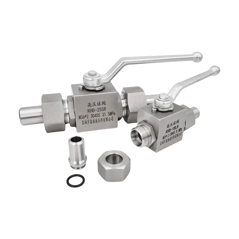
Ball valves paired with pneumatic actuators come in several body configurations, and the choice affects installation space, maintenance access, pressure rating, and cost. The main configurations are two-piece, three-piece, and top-entry designs.
The most common and economical construction. The body is split at one end cap joint. To remove the ball and seats for inspection or replacement, the valve must be removed from the pipeline and partially disassembled. Two-piece ball valves dominate applications in sizes DN15–DN100 (1/2"–4") because they balance cost and performance effectively. They are available in floating-ball and trunnion-mounted configurations.
Three-piece bodies allow the center section (containing the ball and seats) to be removed from the pipeline without disturbing the end connections — the end caps (or "end bodies") remain bolted to the pipe. This in-line serviceability makes three-piece ball valves the preferred choice in hygienic (food, beverage, pharmaceutical) and clean-in-place (CIP) applications where frequent cleaning and seat replacement are routine. They typically cost 20–40% more than equivalent two-piece designs but recover the premium through reduced downtime during maintenance.
In a floating ball valve, the ball is not mechanically supported at both poles — it floats freely between the seats and is pushed by line pressure against the downstream seat to form the seal. This design works well up to roughly DN150 (6") and Class 600. At larger sizes and higher pressures, the bearing load on the downstream seat becomes excessive, causing accelerated wear.
A trunnion-mounted ball valve adds upper and lower trunnion pins that bear the radial load of the ball, preventing it from being pushed hard against the seats by line pressure. The seats in a trunnion design are spring-loaded and move toward the ball to make contact, rather than the ball moving toward the seats. This dramatically reduces operating torque at high pressures and extends seat life. Trunnion ball valves are standard for sizes above DN150 or above ASME Class 600, and virtually all large-diameter pipeline valves are trunnion-mounted.
The adaptability of the pneumatic actuator ball valve across different media, pressures, and temperatures makes it the workhorse of automated industrial fluid control. Below is a sector-by-sector breakdown of typical applications and the specific design features they require.
| Industry | Typical Application | Key Specification Requirements |
|---|---|---|
| Oil and Gas Upstream | Wellhead isolation, pig launcher/receiver | NACE MR0175, sour service, full bore, trunnion |
| Chemical Processing | Acid/solvent isolation, reactor feed control | Hastelloy or lined body, PTFE seats, fire-safe design |
| Water Treatment | Filter backwash, chlorination dosing, tank isolation | Stainless or PVC body, high cycle life (500,000+) |
| Food and Beverage | CIP/SIP, ingredient dosing, tank outlets | 3A/EHEDG approved, 316L SS, electropolished, 3-piece body |
| Pharmaceutical | Pure steam, WFI distribution, batch reactor | Ra <0.4 µm surface finish, full traceability, cleanroom assembly |
| Power Generation | Cooling water, fuel gas, ash slurry | High-pressure Class 900/1500, abrasion-resistant trim |
| Pulp and Paper | Pulp stock, black liquor, bleaching chemicals | Large bore, abrasion-resistant seats, high-torque actuator |
Two regulatory and safety requirements significantly influence ball valve specification in process industries: fire-safe design and fugitive emission control.
PTFE and nylon seats, while excellent under normal operating conditions, will melt and burn in a fire. A fire-safe ball valve incorporates a secondary metal-to-metal seat or a graphite backup ring that engages when the soft seats are destroyed, limiting leakage past the ball to a defined maximum rate during and after fire exposure. Testing per API 607 (quarter-turn valves) or API 6FA (fire testing) verifies this performance. Specifications for valves handling flammable or toxic hydrocarbons in refineries, terminals, and offshore platforms almost universally mandate fire-safe design. The test standard requires valves to maintain acceptable leakage after 30 minutes of exposure to a 760–870°C (1400–1600°F) flame followed by a water spray test.
Fugitive emissions — leakage through the valve stem packing to atmosphere — are regulated under programs such as the US EPA Method 21 (VOC leak detection), the EU Industrial Emissions Directive, and ISO 15848 (fugitive emissions testing for industrial valves). Ball valves with live-loaded (spring-energized) stem packing maintain seal compression as the packing relaxes over time, significantly reducing fugitive emission rates. The ISO 15848-1 standard classifies stem seal performance into classes A, B, and C, with Class A representing the most stringent — leakage below 50 ppm by volume after 20,000 mechanical cycles. Specifying low-fugitive-emission ball valves at the front-end of a project is considerably less expensive than retrofitting or replacing valves after regulatory audits identify exceedances.
Even a correctly specified pneumatic actuator ball valve will underperform or fail prematurely if installed without attention to a few fundamental requirements. The following practices are derived from manufacturer installation manuals and field experience across diverse industrial settings.
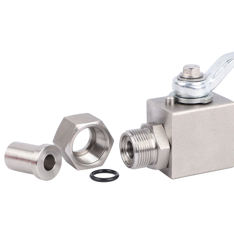
A structured maintenance program dramatically extends the service life of pneumatic actuator ball valves. The following schedule is based on recommendations from leading manufacturers including Metso, Emerson (Fisher), and Flowserve, adapted for general process industry use.
| Symptom | Probable Cause | Corrective Action |
|---|---|---|
| Valve fails to open/close | Insufficient air supply pressure; solenoid valve fault; actuator seal failure | Check air pressure, test solenoid coil, inspect actuator seals |
| Slow stroke time | Flow controller too restrictive; low air pressure; actuator internal friction | Adjust flow controls, verify supply pressure, lubricate actuator |
| Seat leakage (through valve) | Worn or damaged seats; debris on seat face; actuator not reaching end stop | Clean or replace seats, verify actuator travel stops |
| Stem leakage to atmosphere | Worn or compressed stem packing; gland follower loose | Tighten gland follower (within spec) or replace packing |
| Air bleed from actuator exhaust | Piston O-ring failure; cylinder bore scored | Replace O-rings or actuator cylinder |
| Valve position hunting (positioner) | Positioner PID tuning incorrect; air supply fluctuation | Retune positioner, stabilize air supply with accumulator |
Pneumatic actuation is not always the best choice for every ball valve application. Understanding when to specify pneumatic versus electric or hydraulic actuation requires comparing key attributes side by side.
The decision tree is essentially: if compressed air is available and the application is on/off or moderate modulation in a process plant environment, specify pneumatic. If the location is remote, the application requires high-precision positioning, or ATEX requirements make air supply impractical, consider electric. If the torque requirement exceeds what pneumatic can deliver at available air pressure, evaluate hydraulic.

The pneumatic actuator ball valve is not a static technology. Several significant developments over the past decade are changing how these assemblies are specified, monitored, and maintained.
Digital valve controllers (DVCs) — also called smart positioners — go beyond positioning to capture and transmit diagnostic data including valve signature curves (the torque profile through the stroke), travel accumulator data, cycle counts, and deviation alerts. Comparing the current valve signature against a baseline established at commissioning allows detection of seat wear, spring degradation, and packing tightening before they cause a failure. Fisher's FIELDVUE DVC6200 series and Metso's Neles ND9000 are industry-standard examples. Plants using these devices report reductions in unplanned valve-related shutdowns of 30–50% compared to time-based maintenance programs (source: Metso Flow Control white paper, 2021).
WirelessHART (IEC 62591) and ISA100.11a wireless instruments now allow position feedback from ball valves in remote or difficult-to-cable locations without dedicated instrument cable runs. The elimination of signal cable costs — which can reach $50–$150 per meter in offshore or hazardous-area installations — often pays for the wireless hardware within the first project. Battery life for self-powered wireless transmitters typically exceeds 5–10 years at 4-second update intervals, making them practical for long-term monitoring without significant maintenance overhead.
Industrial Internet of Things (IIoT) platforms are increasingly used to aggregate valve health data from across a plant or pipeline network, feeding machine-learning models that predict failure probability based on operating history, process conditions, and maintenance records. The pneumatic actuator ball valve — because of its high population in most process plants and its critical role in safety and production continuity — is one of the primary targets for IIoT condition monitoring investment. Early movers in refining and LNG sectors are reporting reductions in total valve maintenance labor cost of 15–25% through optimized condition-based maintenance programs enabled by continuous valve monitoring data.
Recommended Products
Copyright © Yancheng Yanye Hydraulic Parts Co., Ltd. All Rights Reserved
Custom Ball Valve Factory
China Ball Valve Manufacturers




 English
  русский
  Español