A valve actuator is a mechanical device that opens, closes, or modulates a valve automatically — eliminating manual operation and enabling precise flow control in pipelines, HVAC systems, water treatment plants, and industrial processes. Whether pneumatic, electric, or hydraulic, the right actuator determines how reliably your system performs under pressure, temperature, and cycling demands.
3 Main actuator drive types
±0.5% Typical positioning accuracy
100,000+ Operating cycles before service
How Valve Actuators Work: The Core Mechanics
Every valve actuator converts an energy source — compressed air, electrical power, or pressurized hydraulic fluid — into mechanical motion. That motion either rotates a quarter-turn valve (ball valve, butterfly valve) or strokes a linear valve (globe valve, gate valve). The actuator receives a command signal, applies torque or thrust, and drives the valve to the target position.
In a typical pneumatic actuator setup, a 4–20 mA control signal from a distributed control system (DCS) commands a positioner, which converts that signal into air pressure directed to one or two sides of a piston or diaphragm. The resulting mechanical force drives the valve stem. Electric actuators skip the pneumatic stage entirely: a motor, gearbox, and integrated controller perform the same work using three-phase or single-phase AC power, or DC supply in battery-backed applications.
Position feedback — via potentiometers, encoders, or HART-capable smart positioners — closes the control loop, so the DCS always knows exactly where the valve sits. Modern smart actuators report position, torque, temperature, and cycle count in real time, enabling predictive maintenance strategies that reduce unplanned downtime by up to 40%.
Fail-Safe Behavior: Spring Return vs. Double-Acting
One of the most critical design choices is what the actuator does when power or air supply is lost. A spring-return (single-acting) actuator uses a compressed spring to drive the valve to a predetermined safe position — either fully open or fully closed. A double-acting actuator uses supply pressure on both sides and has no intrinsic fail-safe unless a separate lock-up valve or accumulator is added. For fire-and-gas systems, emergency shutdown (ESD) valves, and overpressure protection, spring-return designs are almost always specified.
Types of Valve Actuators and When to Use Each
P
Pneumatic Actuators
Powered by compressed air (typically 3–7 bar supply pressure), pneumatic actuators are the most widely used type in process industries. They respond quickly — a 6-inch butterfly valve can stroke fully in under 1 second — and are inherently safe in explosive or flammable atmospheres because no electric spark risk exists at the valve. Diaphragm actuators suit modulating service at lower torques; piston actuators handle high-torque or long-stroke applications.
- Best for: chemical plants, refineries, offshore platforms
- Supply pressure: 3–7 bar (44–102 psi)
- Speed advantage: sub-second stroking possible
- Drawback: requires clean, dry instrument air infrastructure
E
Electric Actuators
Electric valve actuators use an electric motor coupled to a multi-stage gearbox. They require no compressed air infrastructure, making them ideal for remote locations, water and wastewater facilities, and HVAC installations. Multi-turn electric actuators handle gate valves and globe valves requiring many turns of the handwheel to travel full stroke. Part-turn (quarter-turn) electric actuators drive ball and butterfly valves. Most modern units integrate fieldbus protocols — PROFIBUS, Modbus, FOUNDATION Fieldbus, or HART — for full remote diagnostics.
- Best for: water/wastewater, power generation, HVAC, remote sites
- Position accuracy: ±0.1° to ±0.5° depending on encoder resolution
- Speed: slower than pneumatic, typically 10–60 seconds full stroke
- Advantage: no air supply needed, precise positioning
H
Hydraulic Actuators
Where extreme torque or force is required — subsea pipeline isolation valves, large dam sluice gates, power plant main steam isolation valves — hydraulic actuators are unmatched. Operating at pressures of 70–350 bar, a compact hydraulic cylinder can generate tens of thousands of newton-meters of torque. They are inherently stiff (not prone to drift under load) and can maintain position without continuous energy input using a hydraulic lock. The main trade-off is complexity: hydraulic power units (HPUs), accumulators, and fluid maintenance add cost and footprint.
- Best for: subsea, large pipeline valves, power plant steam systems
- Torque output: up to 500,000 Nm and beyond
- Operating pressure: 70–350 bar
- Drawback: requires HPU, fluid disposal, leak management
Valve Actuator Type Comparison: Key Parameters at a Glance
Selecting the correct actuator type requires weighing several interrelated parameters. The table below summarizes the most important performance and suitability factors across the three primary drive technologies.
Table 1 — Comparative overview of pneumatic, electric, and hydraulic valve actuators across critical selection criteria.
| Parameter |
Pneumatic |
Electric |
Hydraulic |
| Stroking Speed |
Very Fast (<1 s) |
Moderate (10–60 s) |
Fast (adjustable) |
| Maximum Torque |
Medium (up to ~20,000 Nm) |
Medium-High (up to ~50,000 Nm) |
Very High (500,000+ Nm) |
| Hazardous Area Suitability |
Excellent (no spark risk) |
Good (EEx-rated motors) |
Good (HPU located remotely) |
| Infrastructure Required |
Instrument air system |
Electrical power supply |
Hydraulic power unit |
| Fail-Safe Simplicity |
Simple (spring return) |
Battery/capacitor backup |
Accumulator required |
| Typical Position Accuracy |
±0.5% |
±0.1–0.5% |
±0.5–1% |
| Maintenance Complexity |
Low–Medium |
Low |
High |
| Initial Cost |
Low–Medium |
Medium |
High |
Sizing a Valve Actuator: What the Numbers Actually Mean
Undersizing an actuator is one of the most common — and costly — mistakes in valve system design. An actuator that cannot reliably overcome the break-away torque of a seized or dirty valve will fail to operate when it matters most. Oversizing wastes capital and increases water hammer risk in fast-stroking applications.
Torque and Thrust Requirements
The required actuator output torque must exceed the maximum valve operating torque across all conditions — not just clean-service bench testing. Engineers apply a safety factor of 1.25 to 1.5 on the valve manufacturer's stated torque figures, accounting for wear, differential pressure, packing friction, and temperature effects. For a ball valve rated at 400 Nm under design conditions, the actuator should be selected to deliver at least 500–600 Nm.
For linear valves (globe, gate, diaphragm), the relevant parameter is stem thrust in Newtons or pounds-force. A globe valve with a 100 mm stem diameter, 10 bar differential pressure, and 15% packing friction can require upward of 25 kN of thrust to open against flow. The actuator's rated output thrust must comfortably exceed this figure at minimum supply pressure.
Stroking Time and Process Response
Stroking time matters in two opposite directions. For emergency shutdown (ESD) valves, closing time is critical — SIL-rated ESD systems often specify less than 2 seconds for quarter-turn valves and less than 5 seconds for multi-turn valves. Conversely, modulating control valves in liquid pipelines must not stroke too fast or they risk water hammer: pressure transients that can exceed 150% of normal line pressure within milliseconds, damaging pipe, fittings, and downstream equipment. Slow-close (typically 30–120 seconds) is specified for these applications using flow control valves on pneumatic actuator exhausts or speed-limiting software in electric actuators.
Environmental and Process Conditions
Actuator materials and sealing must match the installation environment. Coastal or offshore applications require stainless steel or epoxy-coated aluminum bodies, corrosion-resistant fasteners, and IP67 or IP68 ingress protection ratings. Cryogenic service — liquid nitrogen or LNG at -196°C — demands special low-temperature elastomers and lubricants rated for extreme cold. High-temperature installations (steam tracing valves above 200°C ambient) require heat-shielded designs and high-temperature grease in gearboxes.
Smart Valve Actuators and Industry 4.0 Integration
The shift from dumb on/off devices to networked intelligent systems is one of the most significant changes in industrial valve technology over the past two decades. Smart electric and pneumatic actuators now embed microprocessors, non-volatile data loggers, and digital communication modules that turn each valve into a data point on a plant-wide industrial network.
Digital Fieldbus Protocols
Modern smart actuators communicate over HART (Highway Addressable Remote Transducer), PROFIBUS PA, FOUNDATION Fieldbus, or newer protocols including PROFINET and EtherNet/IP. HART-capable positioners on pneumatic actuators allow a technician with a handheld communicator to read valve position, air supply pressure, diaphragm pressure, and temperature without touching the actuator physically. FOUNDATION Fieldbus devices can execute PID control loops inside the field device itself, reducing scan cycle load on the DCS and improving control response.
Partial Stroke Testing (PST)
Safety-critical valves — particularly ESD and fire-safe valves — must be proven to operate when needed. Full-stroke testing every valve in an operating plant is often impractical because it requires shutting down process flows. Partial Stroke Testing moves the valve 10–15% of full travel, verifies actuator response and valve freedom, and confirms that the system will function on demand — all without interrupting production. Smart positioners execute and log PST results automatically at user-defined intervals, satisfying IEC 61511 proof-test requirements while keeping the plant running.
40% Reduction in unplanned downtime with predictive diagnostics
10–15% Valve travel used in Partial Stroke Testing
IEC 61511 Safety integrity standard governing ESD valve proof-testing
SIL 3 Highest Safety Integrity Level routinely assigned to ESD valves
Predictive Maintenance via Actuator Diagnostics
Advanced positioners and smart actuators monitor valve signature — the torque or pressure profile as the valve travels from fully closed to fully open. Deviation from a baseline signature indicates developing problems: packing wear that increases friction, seat damage that changes end-of-travel load, or gearbox wear that introduces backlash. Catching these trends months before failure allows scheduled maintenance during planned shutdowns rather than emergency repairs during unplanned outages. One refinery operator reported a 28% reduction in valve-related work orders in the 18 months following deployment of smart positioners across 400 control valves.
Valve Actuator Applications Across Key Industries
No single actuator design serves every industry equally well. The following breakdown illustrates how different sectors prioritize different performance attributes.
Oil and Gas — Upstream and Midstream
Wellhead Christmas tree valves, pipeline isolation valves, and slug catcher inlet valves require actuators rated for sour service (H2S exposure), extreme ambient temperatures (-60°C to +80°C), and ESD functionality. Pneumatic spring-return actuators dominate, with hydraulic actuation used for large-bore mainline isolation valves (DN600 and above). Subsea applications use hydraulic actuators controlled by electrohydraulic umbilicals from surface control systems, with 300+ bar rated housings and full cathodic protection.
Water and Wastewater Treatment
Municipal water systems favor electric multi-turn actuators on gate valves and butterfly valves in pump stations, water towers, and distribution networks. Corrosion resistance in wet, outdoor environments drives material selection — stainless steel or marine-grade epoxy finishes. Many installations use solar-powered electric actuators at remote pump stations where grid power is unavailable. Wastewater plants additionally require actuators rated for continuous duty in H2S-laden atmospheres, necessitating sealed stainless enclosures.
Power Generation
Steam turbine bypass valves, feedwater control valves, and boiler feed pump recirculation valves in power stations operate at elevated temperatures and pressures, requiring actuators with high cycling duty ratings (>1 million cycles for modulating applications) and precise control. Both electric and pneumatic actuators are used, often with manual override handwheels for black-start conditions when instrument air and electrical power are unavailable simultaneously.
Pharmaceutical and Food Processing
Hygienic process requirements govern actuator selection in these industries. Stainless steel diaphragm actuators with electropolished bodies, FDA-compliant elastomers, and clean-in-place (CIP) compatibility are standard on sanitary butterfly and diaphragm valves. Pneumatic actuation dominates because oil-free instrument air avoids contamination risk. Stringent traceability requirements mean actuators must carry material certificates (EN 10204 3.1) for all wetted parts, and position logging is mandatory for batch records in pharmaceutical manufacture.
HVAC and Building Systems
Commercial and industrial HVAC uses electric actuators almost exclusively. Floating control (three-wire, open/close/stop) and modulating control (0–10 V or 4–20 mA) actuators position chilled water, hot water, and steam valves in air handling units, fan coil units, and heat exchangers. Compact size, low noise, and BACnet or LON bus compatibility are valued features. Typical operating torques are low (5–50 Nm), making this the lightest-duty application sector, but energy efficiency and long service life in continuous cycling justify investment in quality components.
Chemical and Petrochemical Processing
Chemical plants often combine the most demanding requirements: corrosive media, high pressures, toxic or flammable atmospheres, and strict process control tolerances. Pneumatic actuators with stainless steel or Hastelloy trim dominate, supported by redundant positioners and air supply systems. Regulatory frameworks including ATEX (Europe) and NEC (North America) classify hazardous areas and dictate actuator enclosure ratings. Many chemical applications also require SIL-rated actuator-valve assemblies with independently audited Safety Integrity Level documentation from TÜV or exida.
Installation, Commissioning, and Maintenance Best Practices
Even the highest-quality actuator will underperform or fail prematurely if installed incorrectly. The following practices reflect lessons learned across thousands of valve installations in demanding industrial environments.
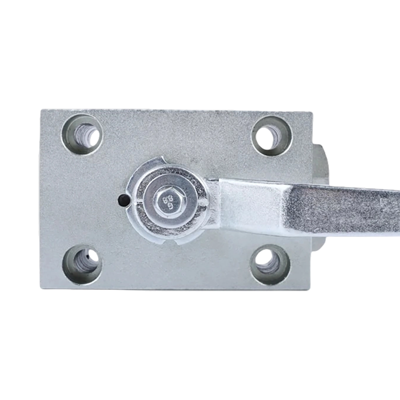
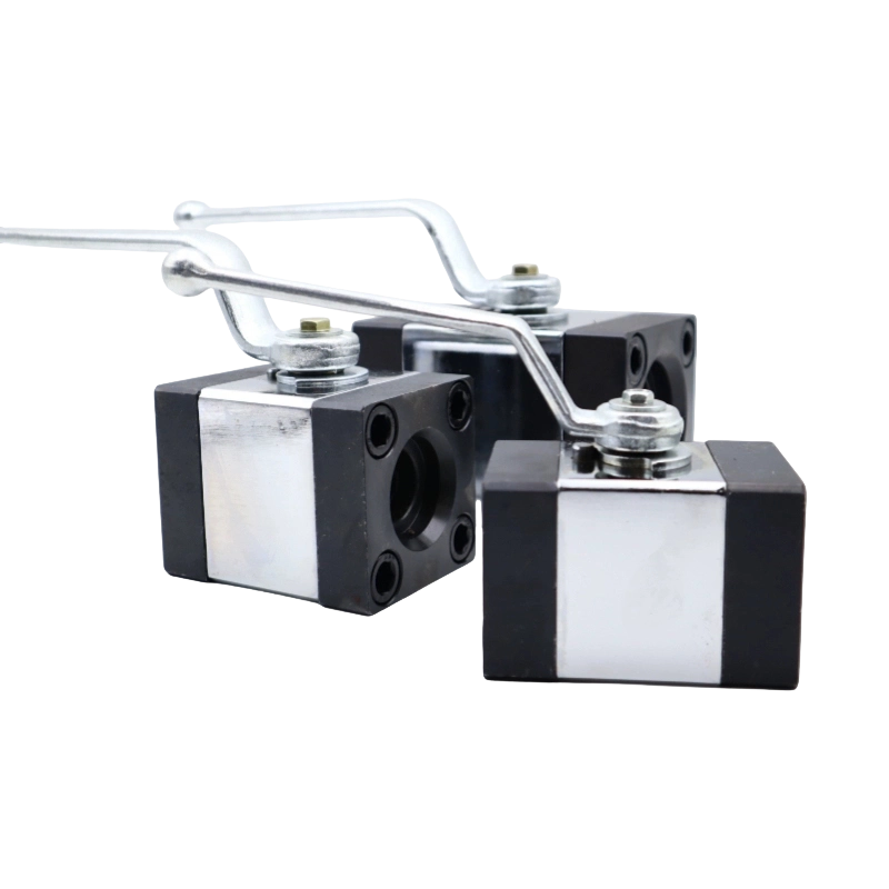
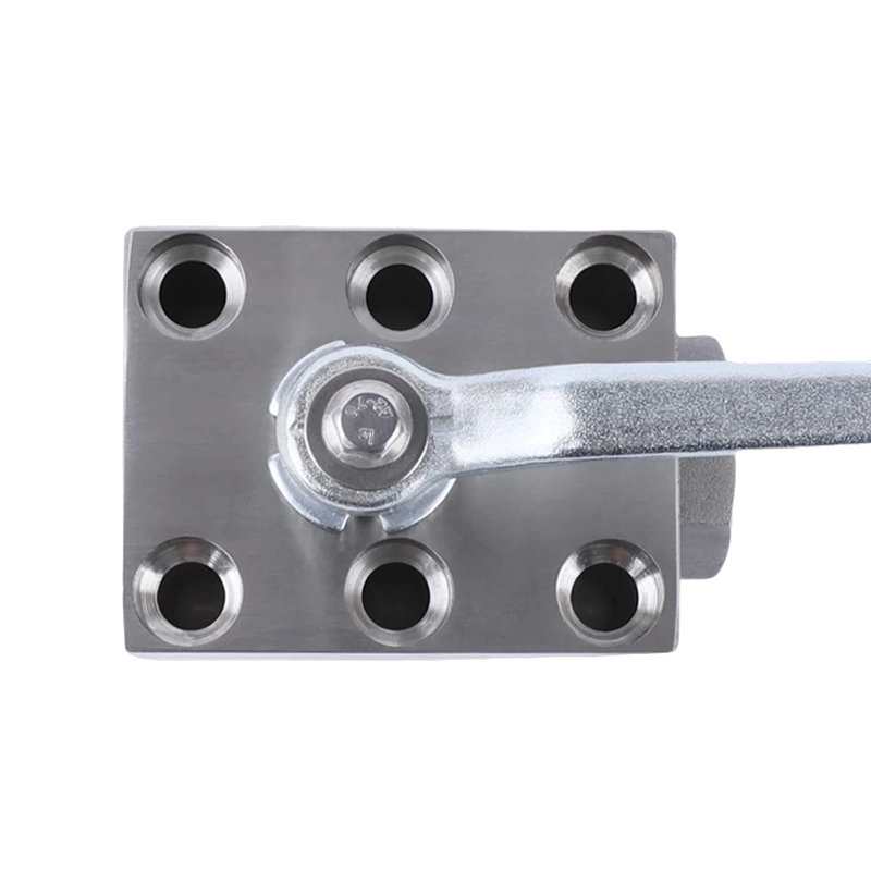
- Confirm valve-actuator mounting compatibility before delivery. ISO 5211 defines standard mounting flange dimensions (F03 through F40) and drive shaft patterns for quarter-turn valves. Confirm that the actuator and valve use matching flanges and shaft profiles — don't assume. A mismatch discovered on-site during turnaround costs far more to resolve than a pre-order drawing check.
- Set mechanical end stops before connecting actuator to valve. The valve's own internal end stops define fully open and fully closed positions. The actuator mechanical stops must be set to match these positions exactly, with the actuator decoupled from the valve stem. Coupling under misaligned stops applies side loads to the valve stem and seats, accelerating wear.
- Verify supply pressure at the actuator, not at the source. Instrument air pressure drops through solenoid valves, positioners, tubing, and fittings. An air supply reading 6 bar at the header may deliver only 4.5 bar at the actuator diaphragm under dynamic demand. Always confirm available pressure at the actuator connection point under operating conditions before sizing is finalized.
- Commission smart positioners with auto-calibration routines. Modern digital positioners include auto-stroke calibration routines that determine the valve's full travel, seat load, and friction characteristics automatically. Running these routines at commissioning establishes a performance baseline and catches mechanical problems — tight packing, actuator spring defects, gearbox binding — before the plant goes live.
- Document and schedule proof tests for safety-critical valves. Any valve in a Safety Instrumented Function must have a documented proof-test procedure, test interval (derived from SIL verification calculations), and records of each test. Partial Stroke Testing can extend the allowable proof-test interval for hard-to-access valves, but full-stroke proof tests cannot be eliminated entirely.
- Inspect instrument air quality annually. Contaminants — moisture, oil carry-over from compressors, pipe scale — degrade positioner nozzle-flapper assemblies, pilot valve seats, and diaphragm materials. ANSI/ISA-7.0.01 specifies instrument air quality: dewpoint at least 10°C below minimum ambient temperature, particle size below 40 microns, oil content below 1 ppm. Plants that neglect air quality spend two to three times as much on positioner and actuator maintenance as those that maintain their air systems.
Key Standards Governing Valve Actuator Procurement
Procurement engineers and instrument engineers must specify actuators against recognized standards to ensure interoperability, safety, and regulatory compliance. The most commonly referenced standards are:
ISO 5211
Defines mounting flange dimensions and drive shaft configurations for part-turn actuators. Ensures interchangeability between actuator and valve from different manufacturers.
IEC 60534
Industrial process control valves standard, covering valve capacity, noise, and leakage. Often referenced alongside actuator specifications for control valve assemblies.
IEC 61508/61511
Functional safety standards for Safety Instrumented Systems. Actuators in ESD or SIS applications must carry SIL certification data including PFD (Probability of Failure on Demand) values.
ATEX / IECEx
Hazardous area equipment directives. Electric actuators in Zone 1 or Zone 2 (gas) or Zone 21 or Zone 22 (dust) classified areas must carry certified Ex markings with appropriate category and gas group designations.
NEMA / IP Ratings
Enclosure ingress protection ratings (IP65, IP67, IP68 under IEC 60529; NEMA 4, 4X in North America) define protection against dust and water. Selection depends on installation environment — indoor clean room vs. outdoor coastal.
API 6D / API 6A
American Petroleum Institute standards for pipeline and wellhead valves. Actuated valves in oil and gas pipeline service are typically procured to API 6D requirements, which include actuator functional testing as part of valve assembly factory acceptance testing.
Common Valve Actuator Failure Modes and How to Diagnose Them
Understanding failure patterns allows maintenance teams to distinguish between actuator faults, valve faults, and instrumentation faults — a distinction that saves hours of diagnostic time in the field.
Table 2 — Common valve actuator failures, probable causes, and recommended diagnostic and corrective actions.
| Symptom |
Probable Cause |
Diagnostic Step |
Corrective Action |
| Valve will not open or close on command |
Solenoid valve failure; loss of air supply; motor overload trip |
Check supply pressure at actuator; verify solenoid energized; check motor thermal overload |
Replace solenoid coil; restore air supply; reset or replace overload relay |
| Valve hunts (oscillates around setpoint) |
Positioner gain too high; I/P converter instability; stiction in valve packing |
Review positioner tuning parameters; perform valve signature test |
Retune positioner; replace I/P converter; adjust packing gland or replace packing |
| Valve fails to reach full open or closed position |
Insufficient actuator torque; mechanical stop misalignment; worn spring |
Measure actuator output torque; check mechanical travel stops; inspect spring condition |
Upsize actuator; readjust stops; replace spring cartridge |
| Positioner feedback reads wrong position |
Feedback linkage loose; potentiometer or encoder fault |
Physically observe valve position vs. feedback reading; inspect feedback connection |
Retighten or replace feedback linkage; replace position sensor |
| Air leak from actuator body |
Diaphragm rupture; O-ring failure; loose bonnet bolts |
Apply leak detection solution around body joints and diaphragm flange |
Replace diaphragm; replace O-rings; torque bonnet bolts to specification |
How to Evaluate and Select a Valve Actuator Supplier
The actuator market is fragmented — hundreds of manufacturers range from global corporations with full service networks to small regional assemblers. The wrong supplier choice creates long-term problems with spare parts availability, technical support, and product quality consistency.
1
Certifications and Third-Party Testing
Require actuators to be accompanied by factory test certificates showing actual torque output, leakage test results, and position accuracy data. For SIL-rated products, require SIL certificates from recognized bodies (TÜV Rheinland, exida). ATEX certificates should be from notified bodies recognized by the appropriate authority in your jurisdiction.
2
Global Service and Spare Parts Network
An actuator that cannot be serviced within 48–72 hours during an emergency has limited value in critical applications. Verify that the supplier has service engineers and spare parts warehouses within a reasonable distance of your facility. Major suppliers like Emerson, Rotork, Flowserve, and AUMA maintain global service networks, but regional manufacturers may offer faster local response in specific geographies.
3
Long-Term Parts Availability Commitment
Industrial valve actuators often remain in service for 20–30 years. A supplier that discontinues a product line three years after purchase leaves users with no path for seal kits, motor replacements, or PCB repairs. Request a formal parts availability commitment — ideally 15–20 years minimum — and verify by checking how the supplier has handled past product line end-of-life situations.
4
Factory Acceptance Testing (FAT) Capability
For critical applications — ESD valves, compressor anti-surge valves, large pipeline isolation valves — conduct a witnessed Factory Acceptance Test at the supplier's manufacturing facility. The FAT should include full-stroke testing at minimum supply pressure, spring-return force verification, position feedback accuracy check, and for SIL-rated actuators, confirmation of PFD data against as-built configuration.


 English
  русский
  Español


")


")

