HOME / NEWS / Industry News / Flow Direction Ball Valve: A Practical Selection and Installation Guide
2026-09-28
Content
The straightforward answer is that most two-way ball valves are bidirectional, but flow direction still matters for three-way valves, unidirectional seat designs, and high-pressure applications where reverse flow can damage the sealing elements. This article explains exactly when flow direction is critical, how to identify it, and how to select the right valve for your pipeline. We will focus on high-pressure ball valves used in oil, gas, hydraulic, and chemical systems, with practical examples from real industrial components. Choosing the correct flow direction is not a theoretical luxury. In a system running at 320 bar, installing a one-way valve in reverse can turn a routine maintenance operation into a shutdown that costs hours of production and repair expenses.
Flow direction in a ball valve defines the path that the fluid takes from the inlet to the outlet when the valve is open. In a standard two-way ball valve, the ball has a straight bore, and the fluid enters on one side and exits on the other. The valve does not care which side is upstream because the two seats are symmetrical. Both seats are made of the same material, are held in place by the same retaining rings, and see the same differential pressure across them.
However, not all ball valves are symmetrical. Some high-pressure ball valves use a single-seat or one-way design. In these valves, the seat is installed on one side only, and the valve has a preferred inlet port. The floating ball is pushed against the seat by the upstream pressure. If the valve is installed backwards, the ball is pushed away from the seat instead of against it, which means the sealing force is lost. You can see immediate leakage at a pressure as low as 50 bar, and at pressure above 320 bar, the seat can be pushed out of position entirely.
To understand the full mechanics, refer to the definition and working principle of high pressure ball valves. That article covers how the ball and seats interact during operation, and why some designs are inherently unidirectional. Even for a bidirectional valve, flow direction can influence the way fine particulate matter settles on the sealing surface. Over time, one side may wear faster than the other if the flow always enters from the same port in a system with particulates. This is especially relevant in natural gas lines where pipeline debris is common.
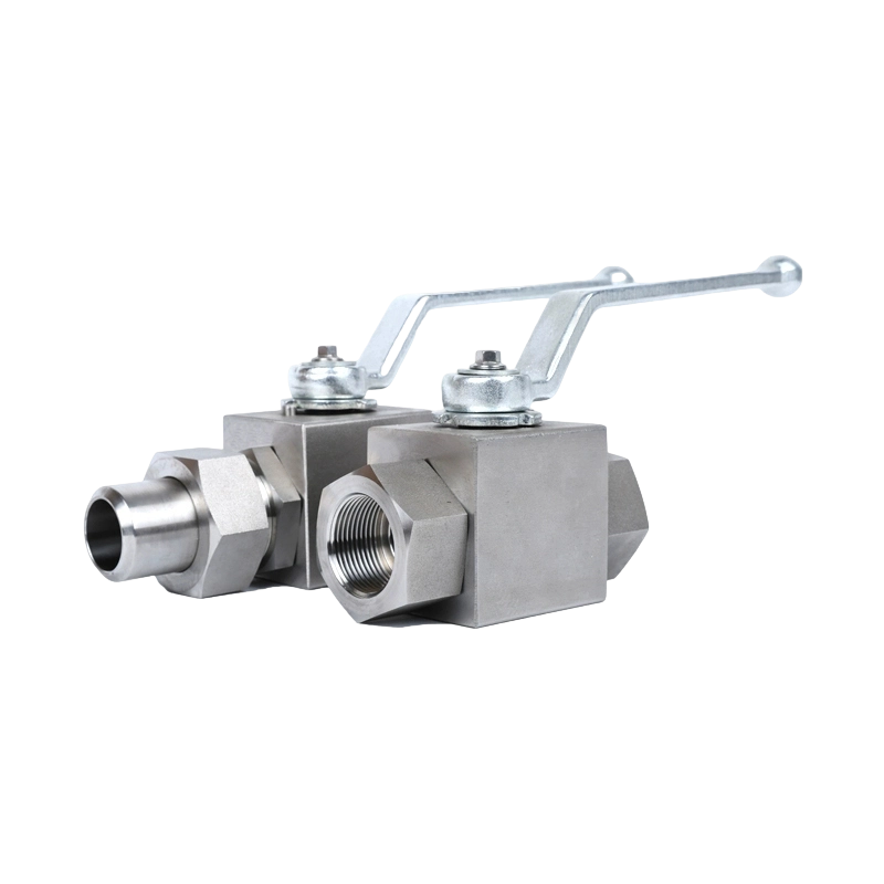
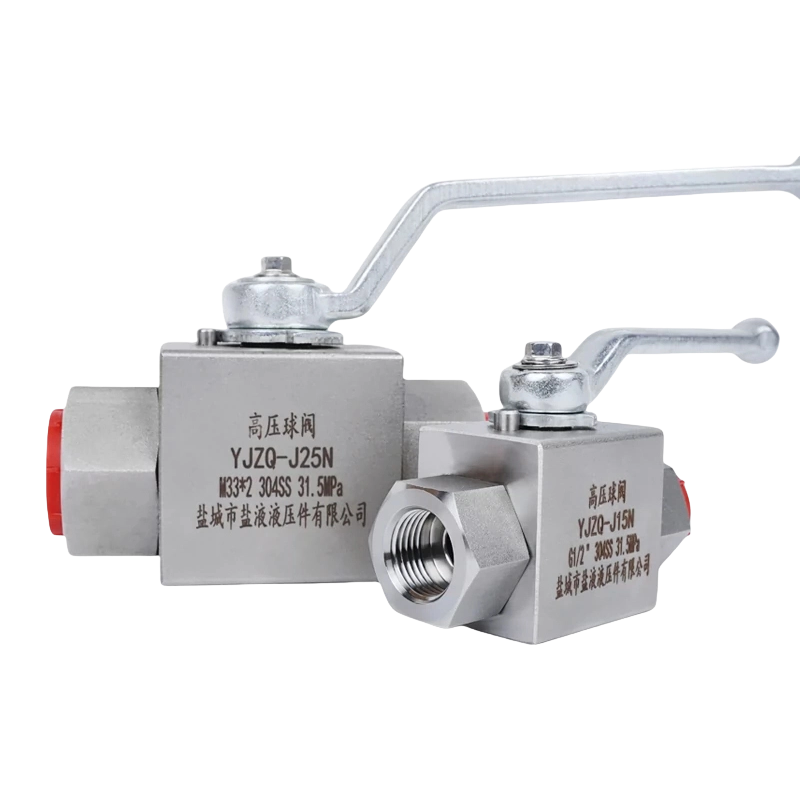 KHB YJZQ Internal Thread High-Pressure Ball Valve for High-Temperature and High-Pressure ApplicationsThis valve offers durable construction in stainless or carbon steel, making it suitable for demanding on/off control in steam, oil, and corrosive media. Its reliable sealing and corrosion resistance address concerns about leakage in high-pressure systems.View Product →
In low-pressure systems, installing a unidirectional ball valve backwards may not cause immediate failure. At 10 bar, the spring-loaded seat or the O-ring can sometimes still create a seal because the residual spring force is enough to keep the ball in contact. But in high-pressure pipelines, the consequences are much more serious. A common symptom is a leakage past the seat, which can escalate to seat extrusion or even a catastrophic blowout. When you are dealing with high-pressure hydraulic oil, natural gas, or CNG, any unplanned leakage creates both an operational disruption and a safety concern.
For example, a high-pressure ball valve rated at 320P (320 bar) is designed with seat materials that are restrained by the body geometry. The seat ring is usually made of POM, PTFE, or a reinforced polyurethane compound. Under normal forward flow, the fluid pressure pushes the ball against the seat, compressing the seat material and creating a tight shutoff. But if the fluid flows from the wrong side, the pressure differential acts in the opposite direction. The seat material is not reinforced for this load path, so it can creep, deform, or even crack. The result is a rapid leak, increased downtime, and potential safety hazards for operators who may be working near the valve.
| Design | Seat Configuration | Flow Direction | Typical Application |
|---|---|---|---|
| Bidirectional | Two symmetrical seats | Either direction | General hydraulic circuits |
| Unidirectional | One active seat | Inlet must match arrow | High pressure gas metering |
| Three-way L-port | L-shaped bore | Port A to B or A to C | Switching between sources |
| Three-way T-port | T-shaped bore | All ports connect | Mixing or bypass systems |
This simplified comparison shows why flow direction cannot be ignored when sourcing high-pressure ball valves. It is not a cosmetic feature; it is a functional requirement. In many real-world cases, a valve that failed after only a few months was not defective. It was simply installed with the arrow pointing the wrong way, and the seat had been progressively worn by the reverse pressure load.
Two-way ball valves such as the KHB and YJZQ series are generally bidirectional. The ball has a straight bore, and the seats are installed on both ends. This means they can be placed in a line without worrying about which end is the inlet. The user can rotate the valve 180 degrees and it will still close correctly. Many industrial maintenance teams prefer this type of valve because it simplifies retrofitting, reduces the chance of a wrong installation, and allows the valve to be used in a variety of line setups.
Three-way ball valves have an L-shaped or T-shaped bore. The flow direction is determined by the port configuration. An L-port valve connects the center port to one of the side ports, while the other side port remains closed. This gives a simple diverting function. A T-port valve can connect all three ports or any two, depending on the handle position. For example, a KHB3K three-way ball valve is often used to divert flow from one source to two destinations, or to blend two streams into one. The correct flow direction must match the intended switching pattern because the L-shaped bore is not symmetric. If you connect the wrong side port as the inlet, the valve may deadhead the line or allow backflow into a closed section.
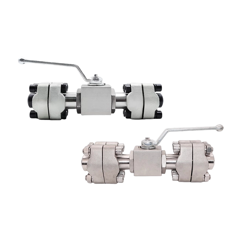
SAE flange ball valves are commonly used in mobile hydraulic systems. They are available with split flange connections, and the flow direction is usually bidirectional because both seats are supported by the flange. However, the O-ring or flange seal can be damaged if the valve is installed in a skewed orientation. When you tighten the flange bolts progressively, any misalignment creates a side load on the valve body. This side load can push the ball off-center, causing a leak path even though the valve was correctly oriented. Always follow the manufacturer's layout drawing and use a torque wrench for the flange bolts.
| Handle Position | L-Port | T-Port |
|---|---|---|
| 0 degrees | A to B, C closed | A to B to C |
| 90 degrees | A to C, B closed | B to C, A closed |
| 180 degrees | B to C, A closed | A to B to C |
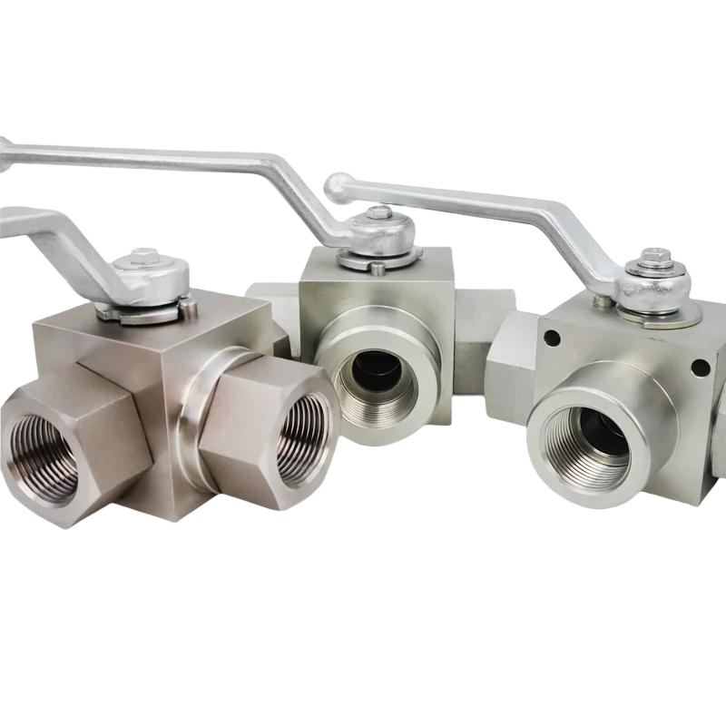
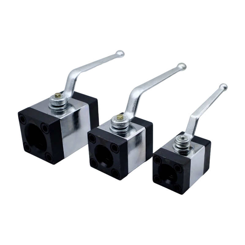
 KHB-3K Three-Way Ball Valve with Mounting Holes for Fluid Distribution and Directional ControlThis three-way valve simplifies complex fluid routing by integrating T or L port functions, while its mounting holes ensure stable installation even under vibration. It supports high-pressure operation up to 31.5MPa, making it a versatile choice for hydraulic and chemical systems.View Product →
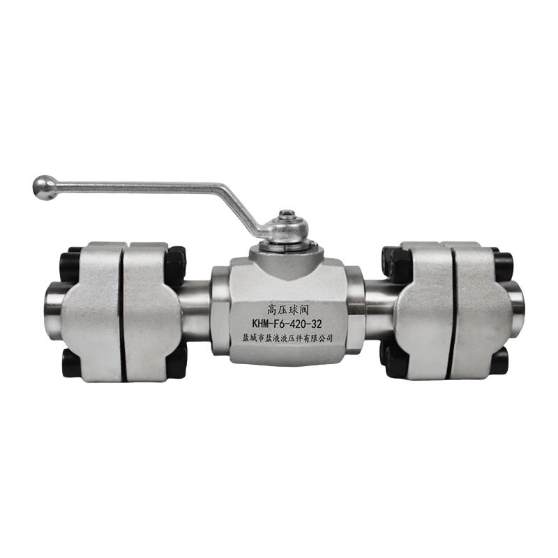
 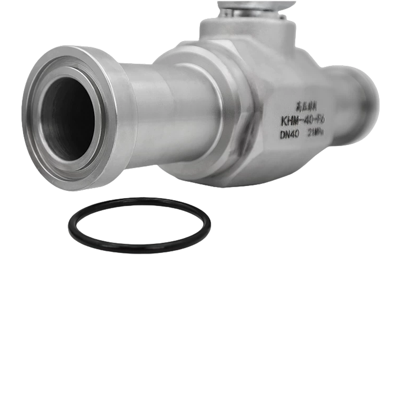 KHM Series Split Flange Ball Valve with Rotatable Flange for High-Pressure SystemsFeaturing a split flange that rotates 360°, this valve eases installation alignment in tight spaces and complex pipelines. Its modular design allows seat replacement without removing the valve from the line, lowering maintenance costs and ensuring reliable bidirectional sealing in high-pressure applications.View Product →
There are several practical ways to determine the flow direction on a ball valve. You should perform at least two of these checks before installing the valve, especially if the body marking is worn or the valve has been in storage for a long time.
In the absence of any markings, never assume a ball valve is bidirectional if it is from an unknown manufacturer or if the bore is not a full-size rectangle. The safest approach is to contact the supplier for the technical drawing. A reputable high-pressure valve manufacturer will provide a dimensional drawing that includes the flow direction arrow, seat orientation, and port numbering. This document should be part of the quotation package.
When selecting a flow direction ball valve for your system, consider the following factors. The choices you make here will affect the lifetime of the valve, the ease of maintenance, and the safety of the overall pipeline.
In our experience, most failures in high-pressure ball valves are caused by improper installation orientation. A clear example is a hydraulic circuit where a valve was installed with the arrow pointing upstream. When pressure peaked at 400 bar, the seat shifted and the valve leaked. By reversing the valve, the problem was resolved without changing the valve itself. This story is not unique. Purchasing managers who understand flow direction are able to reduce warranty claims and spare part consumption by a noticeable margin.
Installation is where flow direction mistakes are most often made. Here is a concise checklist that covers the important points.
For high-pressure systems, we strongly recommend using a quality pipe clamp from our pipe clamp range to hold the valve and adjacent tubing rigidly. This prevents uneven load distribution and extends seat life. In mobile hydraulic equipment, where vibration is constant, a loose valve can transmit the vibration directly to the seat and accelerate wear. A properly mounted valve with a torque-tight pipe clamp will remain in the same position for thousands of operating hours.
No. Standard two-way full-bore ball valves are bidirectional, but some high-pressure, gas, or single-seat designs are unidirectional. Always check the body marking or the manufacturer's data sheet before installation.
In high-pressure systems, the seat can move out of position, causing an immediate leak. Over time, the sealing surface will be damaged, and the valve may not be able to close fully. In gas systems, this can create a minor leak that is difficult to detect by ear but very dangerous in a confined space.
The handle positions and port diagram are the most reliable indicators. On a T-port valve, the middle port can be connected to either side. On an L-port valve, only one side port is connected at a time. If the diagram is missing, use the low-pressure test method described above.
Not directly. The pressure rating is determined by body and seat material. However, incorrect flow direction can cause premature failure at lower than rated pressure, which is a practical risk. For example, a 320 bar valve installed backwards may leak at only 150 bar.
No. Ball valves are not designed for throttling. Partial opening exposes the seat to erosion and can cause the ball to vibrate. For flow control, use a needle valve or fine adjustment valve. This is especially important in high-pressure systems where the flow velocity is high.
Yes. When replacing a valve in an existing line, verify the actual flow direction first. You can trace the line from the pump or source. If in doubt, install a temporary pressure gauge to determine the upstream side. This simple step can save you from a valve failure that occurs days after startup.
Recommended Products
Copyright © Yancheng Yanye Hydraulic Parts Co., Ltd. All Rights Reserved
Custom Ball Valve Factory
China Ball Valve Manufacturers




 English
  русский
  Español