HOME / NEWS / Industry News / Pneumatic Actuated Ball Valve: Complete Selection and Specification Guide
2026-10-05
Content
A pneumatic actuated ball valve is the most cost-effective way to automate on-off control in industrial fluid lines that already have a compressed-air supply. It is simply a quarter-turn ball valve driven by a pneumatic actuator that rotates the ball 90 degrees to open or close the line. The three decisions that determine long-term reliability are the actuator torque margin, the fail-safe position, and the valve body material and pressure class. Make the right calls on these and commissioning is straightforward; get them wrong and the valve will stick, leak, or fail to seat.
This guide explains the working principle, actuator types, critical specifications, torque sizing, material selection, control accessories, and field maintenance, with the practical detail needed to support a real procurement decision.
Compressed air enters the actuator cylinder and pushes one or two pistons. A rack-and-pinion mechanism converts the linear piston travel into 90 degrees of rotary motion on a pinion shaft. That shaft connects to the valve stem, which rotates the ball from the closed to the open position. Reversing the air direction rotates the ball back to the closed position.
In a standard on-off arrangement, a solenoid valve controls the air path. When the solenoid coil is energized, air flows into one cylinder port and exhausts from the other. De-energizing shifts the spool and reverses the flow. The cycle time depends on the actuator size, the solenoid flow coefficient, and the actual air pressure at the inlet.
The core components are:
The ball valve working principle explains how the ball and seats provide a tight shut-off after the stem rotates. Understanding the sealing surfaces helps when comparing leakage classes for gas or liquid service.
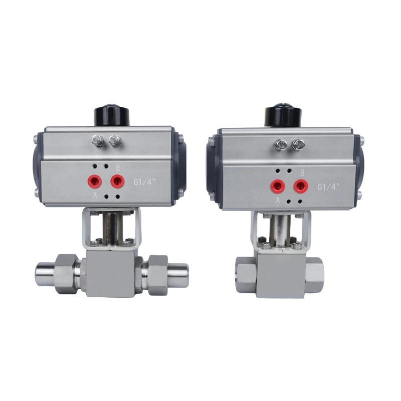
A pre-assembled pneumatic valve package removes the interface risk of matching an actuator to a valve body. For nitrogen and other gas tube circuits, compact stainless steel packages are particularly convenient.
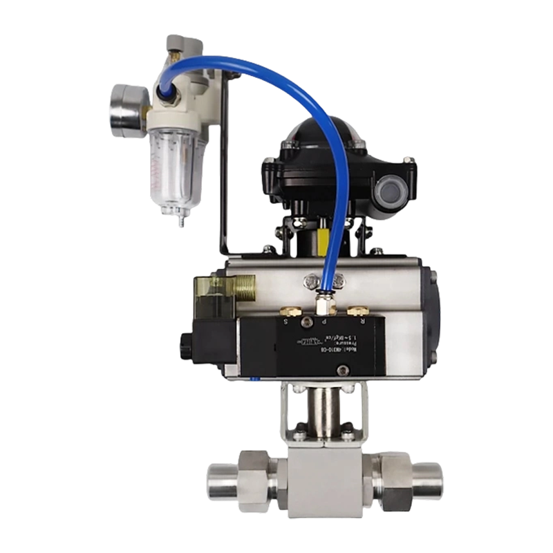 KHB-YJZQ Series 304 Pneumatic High-Pressure Nitrogen Ball Valve (Internal/External Thread)Pneumatic Automation: Equipped with a high-performance pneumatic actuator, enabling remote and fast on-off control, and easy integration into PLC systems.View Product →
The first actuator decision is the behavior on loss of air supply. A double-acting actuator needs air both to open and to close the valve; if the air fails, the valve holds its last position. A spring-return actuator uses air to move in one direction and mechanical springs to return to a defined fail-safe position.
| Feature | Double-Acting | Spring-Return |
|---|---|---|
| Air required to open | Required | Required |
| Air required to close | Required | Not required (spring) |
| Fail-safe position | Holds last position | Open or closed by spring set |
| Torque output | Equal in both directions | Lower on spring end |
| Purchase cost | Lower | Higher |
| Typical service | Stable-air plants | Safety-critical gas, fuel, chemical lines |
Choose spring-return when personnel or process safety requires a deterministic valve position after an air failure. A fail-closed valve on a gas feed line is the typical example. Choose double-acting when the air supply is stable and the cost advantage matters. Note that the spring end of a spring-return actuator produces less torque than the air end, typically 70 to 80 percent of the air-end output, so the spring side must be verified during sizing.
Compile the line conditions and control requirements before requesting quotes. The most common mismatches between ordered valves and actual site conditions are listed below.
| Specification | What to Verify | Effect If Wrong |
|---|---|---|
| Nominal size | DN or NPS matches the pipe bore | Flow restriction, noise |
| Pressure class | PN or ANSI class above maximum line pressure | Body or seal failure |
| Body material | Compatible with fluid and ambient environment | Corrosion, wall thinning |
| Ball and seat material | Rated for temperature and media | Seat leakage, short life |
| End connection | Thread, weld, flange, or plate matches piping | Installation delay and rework |
| Actuator torque | Exceeds break torque with safety margin | Valve will not stroke |
| Air supply pressure | Within actuator nameplate range | Incomplete or slow stroke |
| Fail-safe position | Open, closed, or lock-in-place defined | Safety hazard on air loss |
| Cycle response time | Solenoid Cv and actuator volume | Process upset if too slow |
| Temperature range | Seal and seat material limits | Leakage or stiff operation |
Each item has a direct operational impact. For example, an air supply pressure below the actuator rating reduces the available torque almost proportionally, so a marginally sized actuator will fail during shift change or high-demand periods.
The most frequent field failure in pneumatic actuated ball valves is an undersized actuator. The valve looks correct on paper, but at site conditions the ball will not break free from the seat, or the stroke takes several seconds longer than the process allows.
Actuator output torque must exceed the valve break torque, which is the torque required to start the ball rotating from rest. Break torque is higher than running torque because static friction of the seats and the differential pressure force act on the ball surface. A minimum safety margin of 25 to 30 percent above the break torque is standard for clean fluid service. For media with solids, sticky substances, or high cycle rates, use 50 percent or more.
Here is a practical example. A DN25 ball valve in a 320 bar hydraulic line has a rated break torque of 40 Nm. With a 30 percent margin, the actuator must deliver 52 Nm at the lowest expected supply pressure. If the actuator is rated for 40 Nm at 6 bar but the site air supply delivers only 5.2 bar, the actual output drops to approximately 35 Nm. The valve would not open reliably. Torque calculations must therefore combine the actuator torque curve with the real supply pressure at the actuator inlet, not the nominal plant pressure.
For spring-return actuators, repeat the sizing check on the spring end because the spring torque diminishes as the valve moves toward the end of the stroke. An actuator that is adequate on the air end may be weak on the spring end, producing a slow close or an incomplete seat.
Body material determines pressure containment and chemical compatibility. In high-pressure hydraulic and gas systems, 304 and 316L stainless steels are the preferred choices because of corrosion resistance, strength at elevated temperature, and long service life. Carbon steel is a lower-cost alternative for non-corrosive fluids in dry indoor environments.
Seat material governs leakage and temperature limits. PTFE seats give excellent sealing at moderate temperatures and are common in gas service. Nylon seats handle higher pressure and temperature and tolerate more cycles. For special high-temperature or high-pressure combinations, metal seats are used but with a higher leakage class.
End connections affect installation, maintenance, and the risk of leaks:
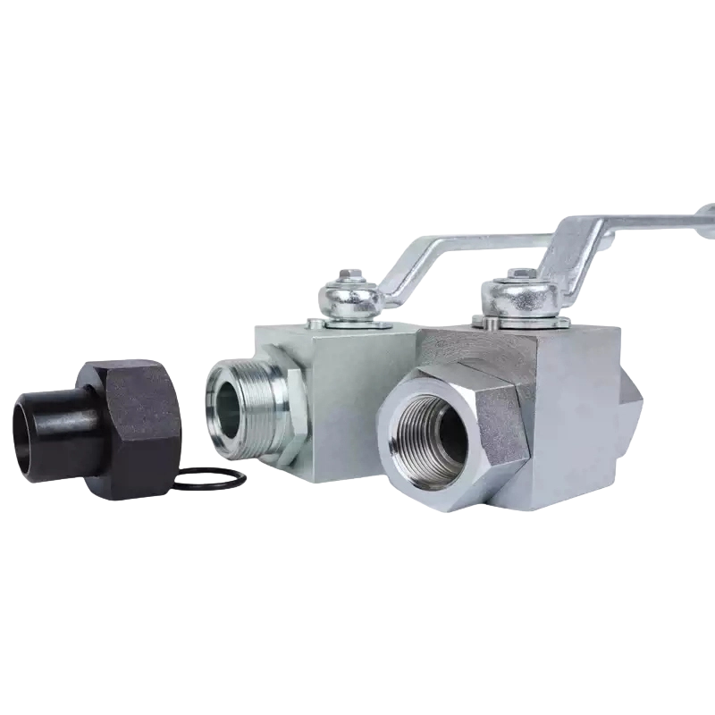
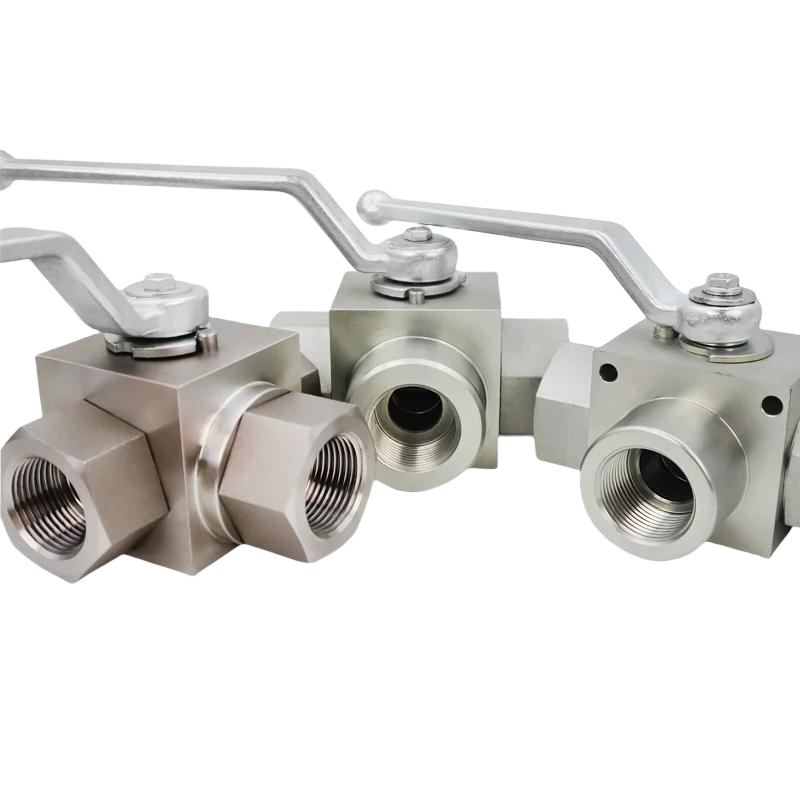
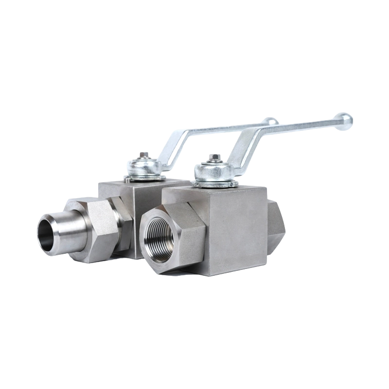
A detailed ball valve buyer guide can help match these options to the specific duty. For high-pressure hydraulic circuits, the KHB/YJZQ series covers internal thread, external thread, welded, and flange connections in one family, which simplifies procurement and spare-part management.
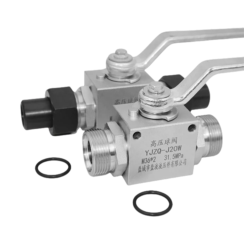 KHB Hydraulic High-Pressure Ball Valve YJZQ Internal/External Thread Welded Ball Valve, StFeature & AdvantagesView Product →
A bare pneumatic actuated ball valve normally needs at least two accessories before it can be wired into a control system. The most common additions are:
For fail-safe duty, select a spring-return actuator with the appropriate spring set. Fail-closed suits fuel and gas lines that must shut when air is lost; fail-open suits cooling-water lines that must continue flow. A lock-up valve can trap air in the actuator to hold the valve position temporarily, but this is not a permanent fail-safe solution because internal leakage will eventually bleed down the trapped air.
Pneumatic actuated ball valves are the workhorse of automated on-off control in plants with compressed air available. The most common duties are:
For gas service, the seat material and the site leak-test method are critical. A soft-seated ball valve achieves near-zero leakage in the closed position, which is why it dominates natural gas and nitrogen applications.
For hydraulic panels and high-pressure manifolds, plate-type ball valves bolt directly to the panel face, reducing piping complexity and saving space.
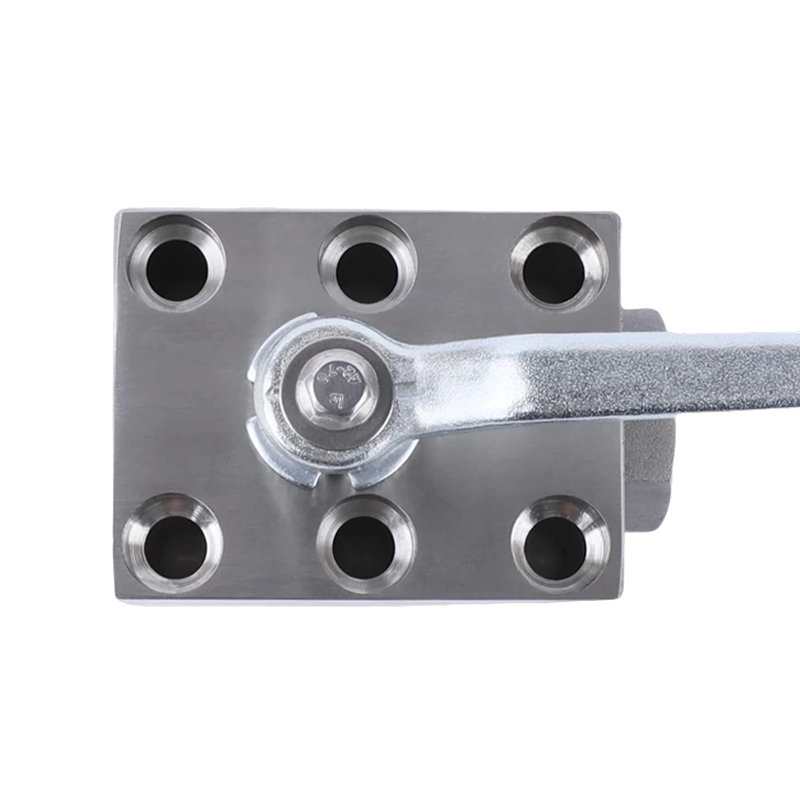 KHP Type (PKH Type) Plate Type High-Pressure Ball Valve, 304 Stainless Steel Plate Ball VaCore Product HighlightsView Product →
Correct installation is as important as correct selection. Mount the actuator above the valve in a horizontal or vertical pipe run, avoiding positions where condensation can collect in the actuator housing. Always support the pipe near the valve so pipe weight does not distort the body flanges or thread joints.
The air supply must be clean, dry, and regulated. Filtered instrument air at the rated pressure significantly extends actuator seal life. After installation, stroke the valve several times and verify that the position feedback matches the actual open and closed states. For gas lines, perform a leak test at line pressure before commissioning.
| Task | Interval | Reason |
|---|---|---|
| Check air filter element | Quarterly | Moisture and particles shorten seal life |
| Inspect solenoid valve operation | Quarterly | Coil failure and sticking spool are common |
| Stroke test the valve manually | Six months | Detects slow movement and seat wear |
| Replace actuator seals and O-rings | 2 to 3 years or 1 million cycles | Restores torque output and airtightness |
| Verify coupling and bracket tightness | Annually | Backlash changes stroke timing |
The three most common faults are an air-starved actuator, a failed solenoid coil, and a loose coupling between the actuator pinion and the valve stem. All are simple to diagnose when position feedback is monitored.
A pneumatic actuator uses compressed air, while an electric actuator uses a motor and gearbox. Pneumatic units stroke faster, and they can be made fail-safe with springs without an external power source. Electric actuators are useful where no air supply exists but are heavier, slower, and more expensive at higher torque ratings.
Most industrial pneumatic actuators are rated for 4 to 8 bar. The nameplate lists the rated range. Below the minimum pressure the torque output falls and the valve may only partially stroke; above the maximum, seals can fail or the actuator can become unstable.
Fail-open means the valve moves to the open position when air supply is lost; fail-closed means it moves to the closed position. The behavior is fixed by the spring set inside a spring-return actuator. Fail-open is common in cooling-water lines; fail-closed is common in fuel and gas lines.
Choose spring-return whenever the valve must reach a defined position after air failure. Choose double-acting when the air supply is stable, the valve may safely stay in its last position, and initial cost matters. For safety-critical lines, spring-return is the standard.
Use a minimum factor of 25 to 30 percent above the valve break torque. Use 50 percent or more for fluids with particles, sticky media, high cycle rates, or uncertain friction. Always check torque at the lowest expected air supply pressure.
A standard ball valve is designed for on-off service. Using it for throttling causes uneven seat wear and unstable flow. For modulation, choose a characterized control ball valve or a conventional control valve fitted with a positioner.
A pneumatic actuated ball valve gives you fast, reliable automated shut-off at a lower total cost than most electric alternatives, provided the actuator torque, fail-safe behavior, and valve materials are matched to the real line conditions. The failures that send maintenance teams into the field are rarely in the valve casting; they are in actuator sizing, air quality, and accessory wiring.
Buying the valve body, actuator package, and mounting accessories from a single production source reduces interface risk and makes spare parts easier to manage. If you are planning a high-pressure hydraulic, natural gas, or nitrogen automation project, a review of a factory-built high-pressure ball valve range is a sensible first step before finalizing your specification.
Recommended Products
Copyright © Yancheng Yanye Hydraulic Parts Co., Ltd. All Rights Reserved
Custom Ball Valve Factory
China Ball Valve Manufacturers




 English
  русский
  Español