
2026-03-02
Content
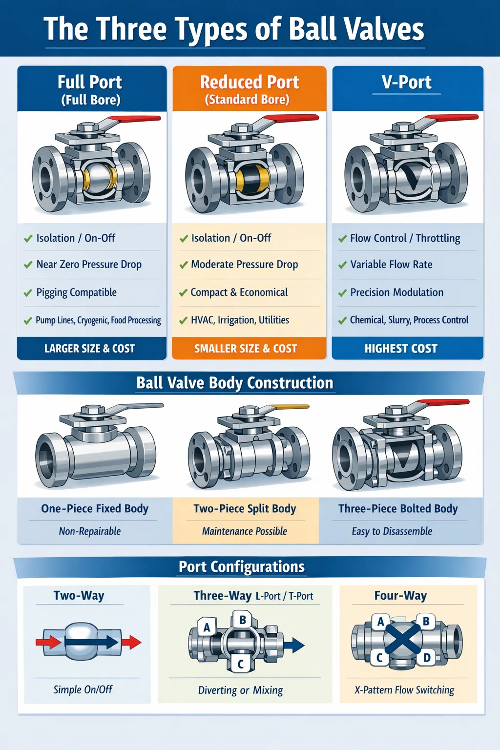
Ball valves are categorized into three primary types based on their bore design: full port (full bore), reduced port (standard bore), and V-port ball valves. Each type serves distinct flow control purposes across industrial, commercial, and residential piping systems. Understanding these differences is essential before selecting a valve for any application, because choosing the wrong type can result in pressure loss, flow restriction, or premature equipment failure.
Beyond bore classification, ball valves are also grouped by body construction — single-piece, two-piece, and three-piece — and by port configuration, including two-way, three-way, and four-way designs. This article covers all of these dimensions in depth so you can make an informed decision when specifying or replacing ball valves in any system.
A full port ball valve, also known as a full bore ball valve, contains a ball with a hole diameter equal to the inner diameter of the connected pipe. When the valve is fully open, fluid passes through without any reduction in cross-sectional area, which means pressure drop across a full port valve approaches zero — typically less than 0.5 psi in standard water service at moderate flow velocities.
This characteristic makes full port ball valves the preferred choice in applications where maintaining line pressure is critical. Common examples include pump suction lines, fire suppression systems, chemical dosing circuits, and high-purity fluid transfer in pharmaceutical or food processing plants. In these environments, even a small pressure drop can disrupt process accuracy or reduce system efficiency.
Full port valves are also the correct selection when a pipeline must be cleaned using a pig — a mechanical device pushed through the pipe to remove deposits or inspect internal surfaces. Because the bore is unobstructed, the pig passes through freely. In contrast, a reduced port valve would trap the pig at the bore restriction.
Full port ball valves are physically larger and heavier than reduced port designs of the same nominal pipe size. A 4-inch full port stainless steel ball valve can weigh 30–50% more than its reduced port counterpart, which increases material costs, support structure requirements, and installation labor. In high-volume infrastructure projects where thousands of valves are specified, this cost differential becomes significant.
Reduced port ball valves, sometimes called standard bore or regular port valves, have a ball with a bore diameter one pipe size smaller than the nominal pipe size. For example, a 2-inch reduced port ball valve will have a bore approximately equivalent to a 1.5-inch pipe opening. This results in a measurable pressure drop, typically in the range of 1–5 psi depending on flow rate and fluid viscosity, but it also produces a more compact and cost-effective valve body.
The reduced bore accelerates fluid velocity through the valve, which can be advantageous in certain self-cleaning applications where higher velocity prevents solids from settling. However, this velocity increase also raises the risk of erosive wear when the fluid contains suspended particles.
Reduced port ball valves dominate general industrial and commercial plumbing applications. They are found in HVAC systems, irrigation networks, compressed air lines, and utility water services. In these contexts, the modest pressure drop is inconsequential, and the lower cost and smaller size make reduced port valves the practical default choice. Roughly 60–70% of ball valves installed in commercial building services are reduced port designs, reflecting their cost-to-performance value in non-critical flow circuits.
V-port ball valves are engineered for throttling and modulating service. Unlike full port or reduced port valves, which are designed primarily for on/off isolation, V-port valves feature a ball with a V-shaped notch machined into it. As the valve rotates, this V-notch progressively opens or closes, providing a characterized flow profile — most commonly an equal percentage or linear relationship between valve position and flow rate.
The V-notch geometry allows for precise control at low flow percentages, where standard ball valves perform poorly. A conventional ball valve opening from 10% to 20% may produce a disproportionately large flow increase, making accurate control difficult. A V-port ball valve, by contrast, delivers consistent, predictable flow increments across the full 0–90 degree rotation range, making it suitable for process control loops.
V-port ball valves are widely used in chemical processing, pulp and paper production, power generation, and water treatment. They handle viscous fluids, slurries, and fibrous media better than globe valves or butterfly valves because the shearing action of the V-notch edge cuts through stringy material and prevents clogging. In wastewater treatment plants, for example, V-port ball valves are frequently specified on sludge lines where conventional control valves would plug within days.
Because V-port ball valves are intended for continuous modulation rather than simple open/close cycles, they are typically paired with electric or pneumatic actuators and integrated into automated control systems. A V-port ball valve operated manually would underutilize its precision capabilities.
| Feature | Full Port | Reduced Port | V-Port |
|---|---|---|---|
| Primary Function | Isolation / On-Off | Isolation / On-Off | Flow Control / Throttling |
| Pressure Drop (Open) | Near Zero | Moderate | Varies by Position |
| Bore Type | Full / Equal to Pipe ID | One Size Smaller | V-Shaped Notch |
| Flow Rangeability | Low | Low | Up to 300:1 |
| Pigging Compatible | Yes | No | No |
| Relative Cost | Higher | Lower | Highest |
| Typical Application | Pump lines, cryogenic, food processing | HVAC, irrigation, utilities | Chemical dosing, slurry, process control |
While bore type defines flow behavior, body construction defines maintenance accessibility and repairability. Ball valves are manufactured in three body configurations, each offering different trade-offs between cost, serviceability, and installation requirements.
One-piece ball valves have a single cast or forged body that cannot be disassembled for internal repair. These valves are sealed during manufacture and are intended as disposable units — when the seat or stem seal wears out, the entire valve is replaced. Their advantage is low cost and a compact profile. They are common in residential plumbing, light commercial applications, and low-pressure gas service where valve replacement costs are negligible.
Two-piece ball valves consist of a main body and an end cap that thread or bolt together. This allows the valve to be partially disassembled for seat replacement or ball inspection without removing it from the pipeline in some configurations. However, complete disassembly typically still requires line removal. Two-piece valves are the most commonly specified design in industrial service, balancing repairability with reasonable cost. The majority of stainless steel and carbon steel ball valves in sizes from ¼ inch to 4 inches are manufactured in two-piece configuration.
Three-piece ball valves have two end caps that bolt to a central body. This design allows the entire internal assembly — ball, stem, and seats — to be removed from the pipeline by unbolting the end caps, leaving the pipe connections in place. This is a major operational advantage in critical service lines where taking a section of piping offline for valve removal would require a full system shutdown. Three-piece valves are more expensive, but in high-value process systems, the reduced downtime during maintenance quickly offsets the higher initial investment. They are standard in pharmaceutical, semiconductor, and high-purity chemical plants.
Port configuration refers to the number of flow paths a ball valve can direct. This dimension is independent of bore type and body construction, adding another layer of classification that is critical for diverting, mixing, or multi-circuit applications.
The standard two-way ball valve has one inlet and one outlet. It functions as a simple shut-off device. This is by far the most prevalent configuration and is what most people refer to when they simply say "ball valve." Two-way ball valves are used wherever a single flow path needs to be opened or closed.
Three-way ball valves have three ports and can be configured in L-port or T-port arrangements depending on the internal bore geometry of the ball.
Three-way ball valves eliminate the need for multiple two-way valves and tee fittings in diverting or mixing circuits, reducing both installation cost and potential leak points. A single three-way valve replaces what would otherwise require two isolation valves and a tee, saving space and reducing pressure drop through the manifold.
Four-way ball valves have four ports arranged in a cross pattern. They are used in applications that require simultaneous flow path switching — for example, reversing the flow direction in a heat exchanger cleaning circuit, or managing complex hydraulic circuits in industrial machinery. Four-way ball valves are less common than two-way or three-way designs and are typically custom-engineered for specific process requirements.
The type of ball valve you select is only part of the specification equation. Seat and seal material selection is equally important and directly affects service life, leak tightness, and chemical compatibility. Ball valve seats are the components that provide the sealing surface between the ball and the valve body, and they must be chemically compatible with the process fluid.
Selecting the wrong seat material is a leading cause of premature ball valve failure. For example, using standard PTFE seats in steam service above 400°F will cause rapid seat deformation, loss of sealing force, and leakage within weeks of commissioning.
Ball valves are also differentiated by how the ball is mechanically supported within the body. This determines the maximum pressure rating, the actuating torque required, and the sealing mechanism.
In a floating ball valve, the ball is not fixed to the stem in the axial direction. It is held in position by the seats and is free to move slightly under line pressure. When pressure is applied, the ball shifts downstream, pressing against the downstream seat to create a tight seal. Floating ball valves are the standard design for valve sizes up to approximately 6 inches and pressure ratings up to ANSI Class 600 (approximately 1440 psi at ambient temperature).
The limitation of floating ball design is that at high pressures or in large sizes, the seating load becomes excessive — the seats must support both the weight of the ball and the full line pressure force, which generates very high operating torque and accelerates seat wear.
Trunnion mounted ball valves fix the ball to both the top stem and a bottom trunnion pin, holding it firmly in position regardless of line pressure. The seats are spring-loaded and press against the ball, rather than the ball pressing against the seats. This reversal of seating force dramatically reduces operating torque and allows the design to handle line pressures exceeding 10,000 psi in high-pressure oil and gas applications.
Trunnion mounted ball valves are standard for sizes 8 inches and above, and for any application above ANSI Class 600 regardless of size. They are the only practical choice for large-diameter pipeline isolation valves, subsea wellhead equipment, and high-pressure hydraulic systems.
Selecting the correct ball valve requires a systematic evaluation of several variables. Treating this as a simple commodity procurement decision leads to frequent misapplication, premature failure, and unplanned maintenance costs. Work through the following decision framework when specifying ball valves.
Following this sequence eliminates most common specification errors. The majority of premature ball valve failures in industrial plants can be traced back to skipping one or more of these steps — particularly inadequate attention to seat material selection and pressure class.
The body material of a ball valve must resist corrosion, erosion, and mechanical stress from the process fluid. The following table summarizes the most commonly specified materials and their corresponding service environments.
| Body Material | Typical Service | Temperature Range | Notes |
|---|---|---|---|
| Brass | Water, gas, low-pressure steam | -40°F to 400°F | Not for ammonia or chlorinated water |
| 316 Stainless Steel | Corrosive chemicals, food, pharma | -320°F to 1000°F | Standard for sanitary and chemical service |
| Carbon Steel (A216 WCB) | Oil, gas, steam, non-corrosive fluids | -20°F to 800°F | Most common refinery and pipeline material |
| Duplex Stainless Steel | Seawater, chloride environments | -50°F to 570°F | Offshore and desalination applications |
| Hastelloy C-276 | Highly corrosive acids, oxidizers | -300°F to 1250°F | Premium cost; used where other alloys fail |
| PVC / CPVC | Water treatment, mild chemicals | 32°F to 210°F (CPVC) | Low cost; not for solvents or high pressure |
Ball valves compete with gate valves, globe valves, butterfly valves, and plug valves across many applications. Understanding where ball valves outperform alternatives clarifies their appropriate use and prevents over-specification.
Compared to gate valves: Ball valves open and close with a 90-degree rotation versus the multi-turn operation of a gate valve. This makes ball valves far faster to operate — quarter-turn actuation takes less than a second versus 20–30 turns for a gate valve. Ball valves also provide better sealing in low-pressure service, where gate valves are prone to seat erosion from wire drawing when throttled even slightly. However, gate valves are preferred in very high-temperature, high-pressure service above 1500 psi where ball valve seat materials reach their limits.
Compared to globe valves: Globe valves provide better throttling control in moderate pressure ranges, but their tortuous internal flow path creates significantly higher pressure drops — typically 3–10 times higher than a ball valve of equivalent size. In applications where energy costs matter, replacing globe valves with V-port ball valves in throttling service can produce measurable energy savings over the system lifecycle.
Compared to butterfly valves: Butterfly valves are lighter and less expensive than ball valves in large diameters (above 8 inches), which is why they dominate large-diameter water distribution and HVAC systems. However, ball valves provide tighter shutoff and handle higher pressures. For sizes below 6 inches in process service, ball valves are generally preferred over butterfly valves due to their superior sealing integrity and better handling of particulate-laden fluids.
Ball valves are among the most maintenance-friendly valve types due to their simple internal geometry, but they are not maintenance-free. Understanding common failure modes extends service life and reduces unplanned downtime.
Ball valves used in regulated industries must comply with applicable design, testing, and material standards. Specifying compliant valves protects against liability, ensures consistent quality, and satisfies inspection requirements. Key standards include:
When purchasing ball valves for regulated service, always request the material test report (MTR), pressure test certificate, and relevant third-party certification documentation from the manufacturer. Valves supplied without traceable documentation should not be installed in safety-critical or regulated process applications.
Recommended Products
Copyright © Yancheng Yanye Hydraulic Parts Co., Ltd. All Rights Reserved
Custom Ball Valve Factory
China Ball Valve Manufacturers
![]()


 English
  русский
  Español


")
")


