HOME / NEWS / Industry News / Ball Valve Sizes Explained Complete Guide: DN NPT Flow Rate Considerations
2026-09-14
Content
The right ball valve size for any application is the one that matches your pipeline connection, carries the required flow coefficient (Kv/Cv), and supports the operating pressure class. That single sentence summarises the entire selection process. Everything else is a detail about how to read datasheets and avoid common mistakes.
In high pressure hydraulic and industrial systems, ball valve sizes normally cover DN6 to DN100. Threaded connections range from 1/8 inch NPT to 2 inch NPT, and flange connections start at DN15. If your line is a 1/2 inch pipe, you will usually order a 1/2 inch ball valve, but you also need to confirm whether the bore is full-bore or reduced-bore. The difference can change the flow capacity by roughly 30 to 40 percent.
A practical example makes this concrete. Put a 1/2 inch full-bore stainless steel ball valve on a hydraulic line moving 12 liters per minute. The pressure drop across the valve will normally stay under 0.5 bar. If the same line uses a 1/2 inch reduced-bore ball valve with a 10 mm ball opening, the pressure drop can rise above 1.2 bar, and the system will lose capacity. In a 315 bar pump circuit, that extra drop is often enough to require a bigger pump or a smaller valve.
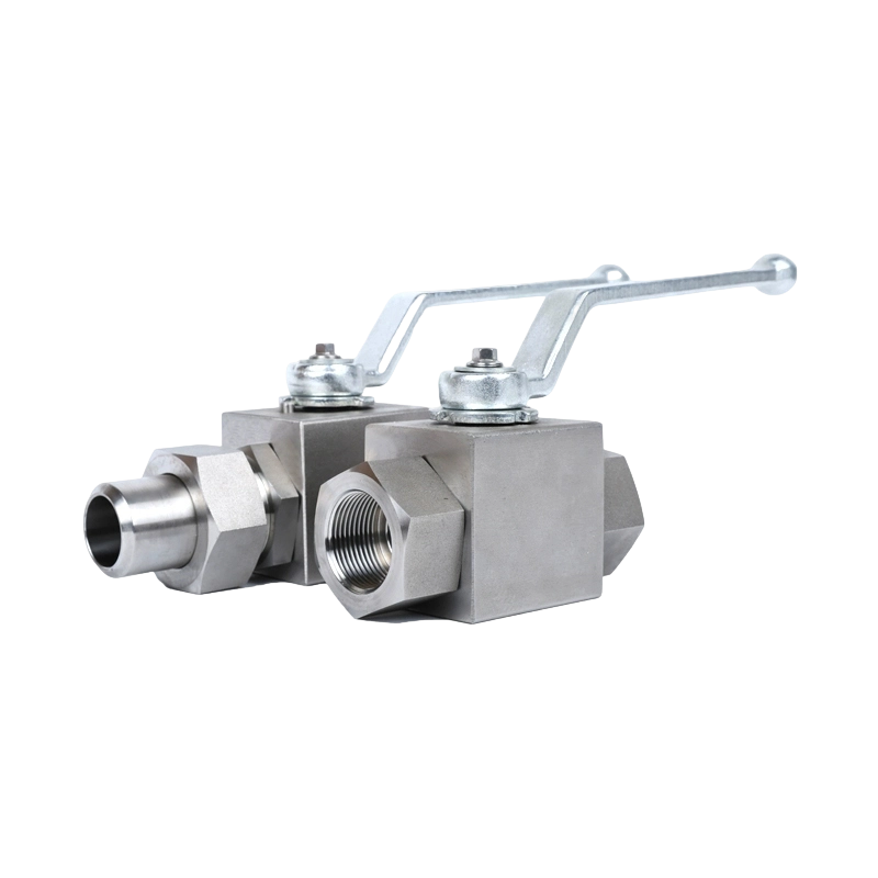
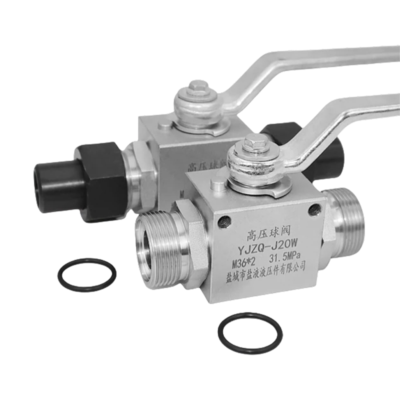 KHB Hydraulic High-Pressure Ball Valve with Welded or Threaded Ends and Optional Pneumatic ActuatorThis valve's welded or threaded connections and stainless steel body suit high-pressure hydraulic lines. Its pressure rating supports the flow and pressure-drop considerations discussed, making it a practical choice for circuits where pressure loss matters.View Product →
The same size can be expressed in several ways. DN is the nominal diameter in millimetres. NPT is the American tapered thread size measured in inches. BSP is the British straight or tapered thread. The actual bore is the real opening inside the valve, and it is the number that matters for flow.
The following table gives a typical reference for full-bore carbon steel and stainless steel high pressure ball valves. The values are representative of common industrial models, not a universal guarantee.
| DN | Thread size | Actual bore (mm) | Approx. flow area (mm²) |
|---|---|---|---|
| DN6 | 1/8 inch | 4.5 | 16 |
| DN8 | 1/4 inch | 6.5 | 33 |
| DN10 | 3/8 inch | 8.5 | 57 |
| DN15 | 1/2 inch | 12.7 | 127 |
| DN20 | 3/4 inch | 17.5 | 240 |
| DN25 | 1 inch | 22.5 | 398 |
| DN32 | 1 1/4 inch | 29 | 660 |
| DN40 | 1 1/2 inch | 35 | 962 |
| DN50 | 2 inch | 46 | 1662 |
There is a common mismatch in the field. A valve labelled 1/2 inch can have a bore of 12 to 13 mm when it is full-bore, or a bore of 9 to 10 mm when it is reduced-bore. The reduced-bore version will conform to a smaller line capacity. This is not just a small loss. The actual flow area can drop by around 45 percent between DN15 full-bore and DN15 reduced-bore.
When you write the specification for a hydraulic skid or a gas line, always state whether you need full-bore or reduced-bore. If the drawing only says 1/2 inch ball valve, the supplier may quote a reduced-bore model, and the commissioning team will later report an unexplained flow deficiency. Read the datasheet and compare the bore table before placing the order.
For a deeper look at the buying process, including how to evaluate a supplier catalogue, see this ball valve buyer's guide.
Flow coefficient is the only reliable way to size a ball valve for real performance. The metric value Kv is the flow of water in cubic metres per hour that passes through the valve at a pressure drop of one bar. The imperial value Cv is the flow in US gallons per minute at a pressure drop of one psi. One Cv is equal to 1.155 Kv.
The basic formula for liquid media is Kv = Q / sqrt(ΔP), where Q is the flow rate in m³/h and ΔP is the allowable pressure drop in bar. For gas media, the formula becomes more complex and should include the absolute pressure and the gas density.
Consider a hydraulic manifold that needs to pass 7.5 m³/h of oil. The pump can tolerate a 0.9 bar drop across the valve. The required Kv is 7.5 / sqrt(0.9) = 7.5 / 0.949 = 7.9. A DN20 full-bore ball valve with a Kv of about 16 will easily cover this requirement. A DN15 with Kv 9 would also work, but only just, and any rise in oil viscosity would make the valve too small.
| Nominal size | DN | Kv (m³/h) | Cv (GPM) |
|---|---|---|---|
| 1/4 inch | DN8 | 2.5 | 2.9 |
| 3/8 inch | DN10 | 4.0 | 4.6 |
| 1/2 inch | DN15 | 9.0 | 10.4 |
| 3/4 inch | DN20 | 16.0 | 18.5 |
| 1 inch | DN25 | 28.0 | 32.4 |
| 1 1/4 inch | DN32 | 45.0 | 52.0 |
| 1 1/2 inch | DN40 | 70.0 | 80.9 |
| 2 inch | DN50 | 110.0 | 127.1 |
These Kv values assume a full-bore ball. For reduced-bore types, expect the Kv to drop to roughly 55 to 70 percent of the full-bore value. The exact number is always available from the manufacturer's datasheet. It is worth the extra time to request it before ordering.
Pressure rating and size are linked by the load on the ball. A DN25 ball valve at 315 bar sees an axial force of roughly 13,000 N, about 1.3 metric tons, on the ball. That force must be absorbed by the stem bearings and the seat. It explains why high pressure valves need thicker stems and heavier handles.
The turning torque of a ball valve grows with the square of the bore. If a DN25 valve at 315 bar needs 8 Nm to turn, a DN50 valve at the same pressure may need around 32 Nm. In practice, operators cannot apply that much force manually, so large high pressure ball valves are fitted with longer handles or an actuator. Do not choose a DN50 manual valve for a 315 bar line unless you are prepared for a hard-to-turn handle.
Seat material also interacts with size. PTFE seats are common up to 180°C and suit DN6 to DN50. PEEK seats can handle 300°C and are more expensive. For large bore valves at high pressure, PEEK is frequently specified to prevent seat extrusion. If you are selecting a valve for steam or hot oil service, the seat material is as important as the pressure class. A high pressure valve with a soft seat will not perform correctly in a 250°C circuit, even if its DN size matches the pipe.
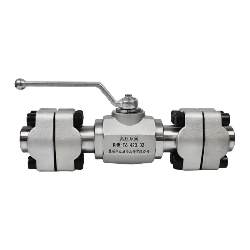
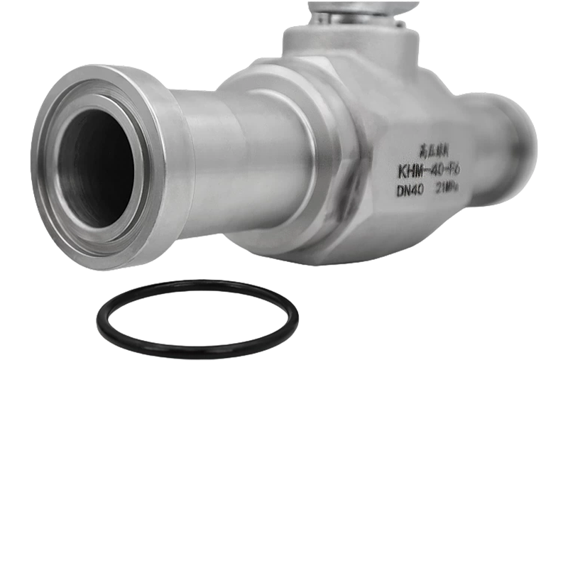 KHM Series High-Pressure Flange Ball Valve with Split Flange DesignThis flanged ball valve offers a split flange that rotates 360°, easing installation alignment. With pressure ratings above 31.5 MPa and full-bore options, it fits high-pressure systems where flange connections define valve size differently than threaded types.View Product →
The connection type is part of the size definition. When an engineer says "a 1/2 inch ball valve", they usually mean a threaded valve with 1/2 inch NPT or BSP threads. But a flanged valve of the same nominal size has completely different physical proportions.
Threaded connections cover DN6 to DN50. They are economical and fast to install, but the thread is not a full-bore match. A 1/2 inch NPT thread has an outer diameter of about 20.5 mm, while the nominal pipe size is DN15. If you measure the thread with a caliper, the reading will not be 12.7 mm. This is normal and should not cause concern.
SAE flange connections appear in mobile hydraulics and compact machinery. They are called split flanges in the industry. A DN25 SAE flange ball valve uses the same flange pattern as a 1 inch port. The flange type gives a rigid, leak-resistant connection without threading. It is also easier to remove for maintenance in tight spaces.
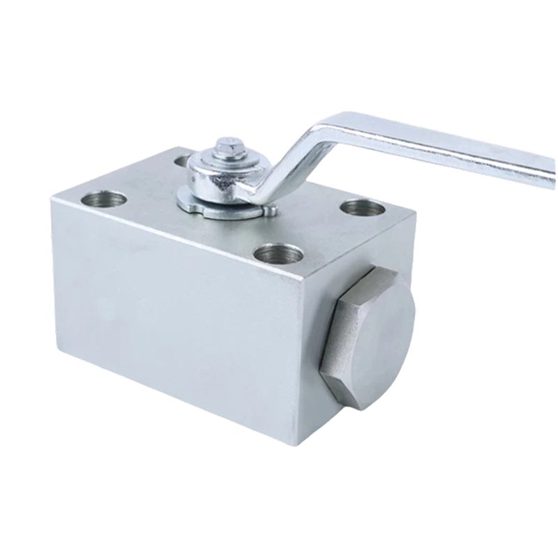
Plate-type versions, such as KHP and PKH, bolt directly onto a manifold. The port spacing is determined by the size and the series. They are ideal for compact control blocks where several valves share one body. Because the body is clamped to the block, no pipe threads are needed, which reduces leak paths in high pressure manifolds.
| Connection | Typical size range | Best application |
|---|---|---|
| NPT / BSP thread | DN6 - DN50 | Hydraulics, compressed air, general industry |
| SAE flange | DN15 - DN50 | Mobile machinery, oil and gas skids |
| ISO flange | DN15 - DN100 | Process industry, chemical plants |
| Plate / manifold | DN6 - DN40 | Control blocks, compact manifolds |
| Welded | DN15 - DN80 | Instrumentation, severe service |
Natural gas, CNG, and LNG lines operate at high pressure and dry conditions. The valve size must match the pipeline and the seat material must be compatible with gas. For a CNG dispensing unit, a bore of DN15 to DN25 is common, operating at 250 bar or higher. Oversizing does not help here because gas velocity in the pipeline will drop and create false pressure readings. Use the nominal size and verify the Kv against the expected gas flow.
 Natural Gas High-Pressure Ball Valve for Transmission and DistributionDesigned for natural gas systems up to PN100, this valve features fire-safe and anti-static construction. Its full-bore flow channel suits high-pressure gas lines where size and seat compatibility are critical, as discussed in the preceding section.View Product →
Hydraulic circuits are different. The pump flow determines the line velocity. For a pressure line, a fluid velocity of 4 to 8 m/s is typical in industrial systems. If a 3/4 inch pressure line transports 30 liters per minute, the velocity is roughly 1.3 m/s, which is already below the recommended range for a pressure line. The ball valve for that line should be a full-bore DN20 to avoid adding a local restriction.
Steam lines require attention to temperature and thermal expansion. A DN40 steam line with saturated steam at 16 bar is a normal size for a 500 kW heat exchanger. Use a stainless steel valve with a PEEK seat and a full-bore passage to avoid steam condensate hammering. The valve body should be rated for at least 25 bar even if the line pressure is 16 bar, because a closed ball in a steam line can create a trapped pressure pocket when it heats up.
For a broad look at why high pressure ball valves outperform other designs in severe service, read this article on advantages of high pressure ball valves.
Sizing errors are rarely discovered until after commissioning. The five mistakes below account for a large majority of valve failures in industrial systems.
| Checkpoint | What to verify |
|---|---|
| Bore type | Full-bore or reduced-bore |
| Connection | NPT, flange, plate, or welded |
| Flow coefficient | Kv / Cv at operating pressure drop |
| Pressure class | 315 bar, 400 bar, or PN class |
| Seat material | PTFE, PEEK, or Nylon |
| Body material | 304, 316L stainless steel, or carbon steel |
DN stands for nominal diameter in millimetres. It is the common reference for pipe and valve sizes. DN15 is a 15 mm nominal size, but the actual bore of a full-bore valve is often 12 to 13 mm because of body wall thickness and thread details.
NPT uses a 60 degree thread angle and a tapered profile. BSP uses a 55 degree angle and is available in parallel or tapered. The thread crest and root dimensions are also different. NPT and BSP fittings are not interchangeable, except for a few sizes where the friction of the pipe seal provides a temporary leak-free joint. Always specify the thread standard in your purchase order.
Cv is the water flow in US gallons per minute at 1 psi pressure drop. Kv is the water flow in m³/h at 1 bar pressure drop. One Cv equals 1.155 Kv. A valve with a Cv of 10 will pass about 10 gallons of water per minute with a 1 psi drop, which is roughly 11.55 m³/h at a 1 bar drop.
Choose full-bore when you need the same flow capacity as the pipe. Choose reduced-bore when flow is comfortably below the pipe capacity and saving space or weight matters. Reduced-bore valves are usually cheaper and lighter, but never use one in a high velocity gas service because the Bernoulli effect and turbulence will wear the seat.
No. A bigger valve adds dead space, increases cost, and often raises the torque. It can also cause a larger pressure drop because the flow has to expand and contract at the valve end. Select the size that matches the line and the flow requirement.
Ball valves are designed for on/off service. Throttling wears the seat and ball quickly because the high velocity jet is directed at a small area of the soft seat. Use a needle valve or fine adjustment valve for flow control, and keep the ball valve fully open or fully closed.
For a threaded valve, measure the outer diameter of the male thread or the inner diameter of the female thread. For a flanged valve, measure the bolt circle diameter and the face-to-face dimension. Compare these values with the manufacturer's dimension sheet. The nominal size is also stamped on the valve body near the handle or on a nameplate.
Start from the pipe connection, then confirm the flow coefficient. For most hydraulic and high pressure water applications, a full-bore stainless steel ball valve in 304 or 316L will perform well when the temperature and pressure stay within the rated limits. Provide the supplier with three numbers before ordering: the flow rate, the allowable pressure drop, and the connection type. These three values are enough to select the correct DN, the correct bore type, and the correct material.
When in doubt, select full-bore. The additional cost is small compared with the downtime caused by an undersized valve. A responsible supplier will always be able to give you the Kv curve for the specific product. If the supplier cannot produce a Kv value, do not rely on the model. The difference between a properly sized valve and a guessed size is often the difference between a smooth run and a stalled process line.
Recommended Products
Copyright © Yancheng Yanye Hydraulic Parts Co., Ltd. All Rights Reserved
Custom Ball Valve Factory
China Ball Valve Manufacturers




 English
  русский
  Español