HOME / NEWS / Industry News / Types of Hydraulic Valves Explained: Pressure, Flow, Directional, and Shut-Off Selection
2026-08-24
Content
When a hydraulic press suddenly cannot reach its specified working pressure, the pump is rarely the root cause. A relief valve opening a few bars early, a worn directional spool leaking across its lands, or a check valve seat holding a small particle will all produce the same symptom: pressure builds to 170 bar instead of 250 bar. The fastest way to diagnose and solve this is to know exactly which hydraulic valve family you are dealing with.
Hydraulic valves divide into four functional families: pressure control, flow control, directional control, and check or shut-off. Each family has a specific role, a set of construction types, and its own failure modes. If you select a valve by function first and by size, material, and actuation second, almost every hydraulic circuit issue becomes easier to prevent, diagnose, and repair.
A hydraulic valve is a mechanical component that controls the pressure, flow rate, or direction of hydraulic fluid in a circuit. It sits between the pump, the tank, and the actuator, and it decides where the oil goes, how fast it moves, and at what pressure it is delivered.
Most hydraulic valves use one of two working principles. Poppet valves close a passage by pressing a conical or spherical element against a precision-machined seat; when the element lifts, oil flows past. Spool valves slide a precision-ground cylinder inside a sleeve; the lands and grooves on the spool connect or block ports as the spool shifts. Poppets give a drop-tight seal but normally connect only one inlet to one outlet. Spools connect several ports in one compact body, but they always allow a small internal leakage, which matters when the job is holding a load over time.
Every valve also relies on throttling to regulate. When a valve is partially open, the passage area is restricted and a pressure drop appears across the orifice. Even a simple restriction can limit flow; the design challenge is to keep that flow stable while the load pressure changes.
Before selecting any valve, you need to know which family it belongs to. The table below is the starting point for any selection, diagnostic, or replacement task.
| Family | Variable controlled | Typical valve types | System purpose |
|---|---|---|---|
| Pressure control | Pressure limit, secondary pressure, load holding | Relief, reducing, sequence, counterbalance | Protect components; determine actuator force |
| Flow control | Flow rate and actuator speed | Throttle, needle, compensated flow control, divider | Set and stabilise the speed of cylinders and motors |
| Directional control | Oil path and motion direction | 2/2, 3/2, 4/2, 4/3 spool and poppet valves | Start, stop, reverse, and sequence actuator movement |
| Check and shut-off | One-way flow and circuit isolation | Check valves, ball, gate, globe, butterfly | Prevent backflow; disconnect a circuit for service |
Pressure control valves protect the circuit from overpressure and determine the maximum force an actuator can produce. They work by comparing hydraulic force against a spring force or a pilot pressure, and they are always set to a defined pressure value.
A relief valve is normally closed. When pressure reaches the set value, it opens and bypasses oil to the tank. It is the last line of protection for the pump and every pressure component. Common practice is to set the relief valve about 5 to 10 percent above the maximum working pressure of the circuit; for example, 260 bar on a system that runs at 250 bar. Direct-acting relief valves respond quickly, while pilot-operated relief valves stay more stable at large bypass flows.
A pressure reducing valve is normally open. It senses the downstream pressure and throttles flow until that pressure equals the set value, which protects sensitive components such as pilot controls, brakes, and clamping circuits. Because the valve passes flow continuously, it must be rated for the flow of the secondary circuit. Most valve manufacturers recommend setting the output 10 to 15 bar above the pressure actually required by the consuming device, so supply fluctuations do not disturb the controlled branch.
A sequence valve is normally closed and opens when the inlet pressure reaches the set value. It supplies a secondary circuit only after the primary action has developed enough pressure. A typical example is a clamping cylinder that must grip the workpiece before a drilling cylinder advances; the sequence valve is set at roughly 80 percent of the main relief pressure so the clamp force is always available first. Remember that sequence valves have hysteresis: they open at one pressure but reseat at a noticeably lower one.
A counterbalance valve maintains backpressure on the return side of a vertical cylinder so a suspended load cannot drop by its own weight. It holds the load even if a line ruptures. Pilot-assisted types open with system pressure and use pilot ratios such as 3:1 or 4.5:1; they are the standard solution for making a hydraulic cylinder move smoothly under an overrunning or negative load.
| Valve type | Normal state | Action at set pressure | Common misapplication |
|---|---|---|---|
| Relief | Closed | Opens and bypasses to tank | Used as a reducing valve, causing overheating |
| Reducing | Open | Throttles to hold downstream pressure | Set too low, starving the actuator |
| Sequence | Closed | Opens to feed a secondary circuit | Used as a relief valve; it does not bypass to tank |
| Counterbalance | Closed | Holds the load until pilot pressure opens it | Adjusted too high, causing jerky lowering |
Flow control valves set the speed of cylinders and hydraulic motors. The rule to remember is that flow through an orifice depends on the pressure difference across it, so if the load pressure changes, a simple throttle will not hold speed.
A throttle valve is the simplest flow restrictor. It is inexpensive and works reasonably when the load is nearly constant. On a machine tool feed where the cutting force changes, however, a simple throttle lets the speed drop as the load increases.
A pressure-compensated flow control valve adds a compensator spool that keeps the pressure drop across the metering orifice constant. Published technical data from major valve manufacturers shows flow stability within roughly 3 to 5 percent over the designed pressure band. This is the correct choice for stable feed rates in machine tools, press feeds, and conveyor drives.
A needle valve uses a fine-pitch threaded stem with a conical point to adjust the orifice area very precisely. Such valves are common in hydraulic test benches, pressure gauge lines, pilot circuits, and metering applications. The product code communicates the rating directly: the suffix 320P means a nominal working pressure of 320 bar, and 400P means 400 bar. For precise flow adjustment in a stainless steel hydraulic circuit, a high-pressure stainless steel metering needle valve handles both throttling and shut-off in one compact body.
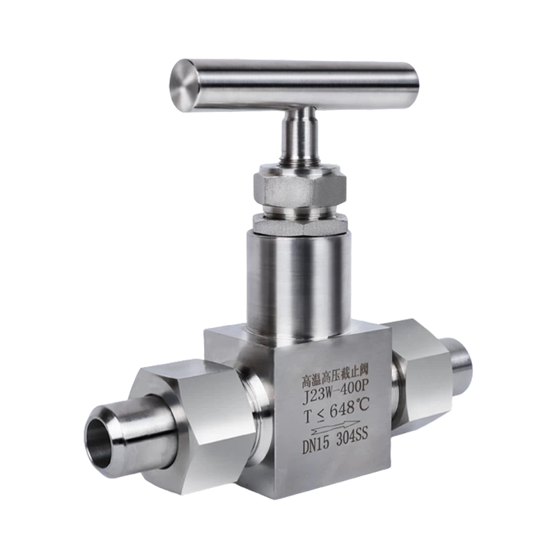 Wholesale J23W-400P 304 Stainless Steel Globe Valve, Needle Valve (High-TemperatYancheng Yanye Hydraulic Parts Co., Ltd is China Custom J23W-400P 304 Stainless Steel Globe Valve, Needle Valve (High-Temperature & High-...View Product →
A flow divider splits one inlet flow into two nearly equal outlets. It is a practical way to synchronize two cylinders without a second control loop. The accuracy of gear-type dividers is typically within a few percent, depending on the load difference between the two branches.
Two installation positions matter for flow control. Meter-in controls the supply flow and suits resistive loads. Meter-out controls the return flow and suits overrunning loads such as vertical cylinders, because it prevents the load from running away under its own weight.
Directional control valves start, stop, and reverse the movement of cylinders and motors. They also select the oil path in a circuit.
The code 4/3 reads "four ports, three positions." The first number is the number of working ports; the second is the number of spool positions. A 2/2 valve is a simple on-off valve, a 3/2 valve serves single-acting cylinders, and a 4/3 valve with a spring-centered spool sends both cylinder ports to tank in the middle position, which stops the cylinder and lets it rest without building pressure.
| Configuration | Number of ports | Number of positions | Typical use |
|---|---|---|---|
| 2/2 | 2 | 2 | Simple on-off isolation |
| 3/2 | 3 | 2 | Single-acting cylinders |
| 4/2 | 4 | 2 | Double-acting cylinder without stop position |
| 4/3 | 4 | 3 | Double-acting cylinder with neutral stop |
A spool valve is compact, can combine many flow paths, and shifts easily under solenoid force, but it cannot seal completely; a small leakage passes across the lands at high pressure. A poppet valve seals drop-tight, which is why pilot-operated poppet and check designs are used to hold clamped loads overnight. The price is a larger body and normally one flow path per element.
Actuation determines what happens when the power disappears. A spring-return solenoid valve returns to its de-energized position, which may be normally open or normally closed depending on the model. A spring-centered 4/3 valve is a safe choice for a press: if power fails, the cylinder stops in place instead of extending or retracting without control.
Check and shut-off valves are not adjustable controllers; they are safety and maintenance devices. They either allow oil to flow in one direction or isolate a section of the circuit completely.
A check valve allows flow in one direction and blocks it in the reverse direction. The cracking pressure is the small pressure required to open the seat, commonly 0.3 to 5 bar depending on the spring. In hydraulic circuits, check valves keep the pump from turning backward, keep the system primed, and isolate branches. For holding a heavy cylinder, you need a pilot-operated check valve, because a standard check valve opens under a small reverse pressure. A straight-through welded stainless steel high-pressure check valve is the typical choice for permanent hydraulic lines that must not leak back.
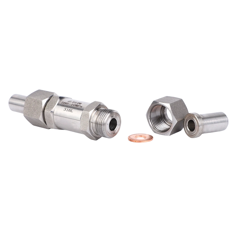 Wholesale Stainless Steel Check Valve, Straight Through Welded High-Pressure CheYancheng Yanye Hydraulic Parts Co., Ltd is China Custom Stainless Steel Check Valve, Straight Through Welded High-Pressure Check Valve, Z...View Product →
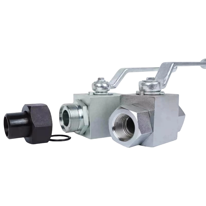
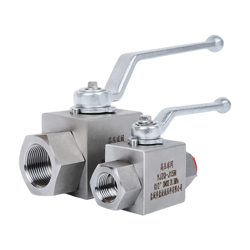
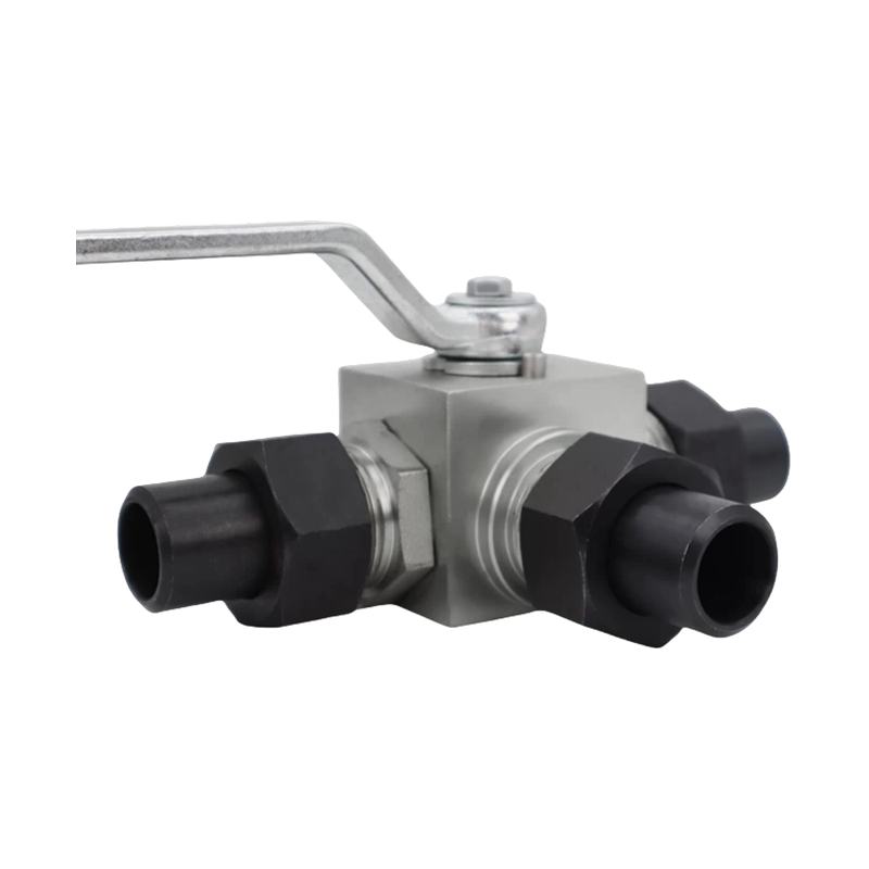
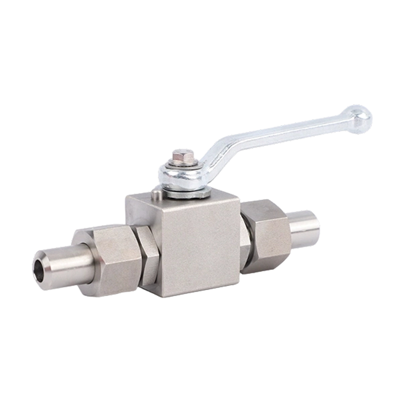
Ball valves are quarter-turn shut-off valves. Ninety degrees of handle movement takes the valve from fully open to fully closed, which makes them ideal for the quick isolation of a pressure line before maintenance. The KHB/YJZQ series, for example, uses internal or external threads and welded connections, and is available in 304 stainless steel, 316L stainless steel, or carbon steel. If you need to understand port sizes, seat materials, and pressure ratings in more depth, our hydraulic ball valve buyer's guide walks through every selection point. As one practical example, a KHB/YJZQ series hydraulic high-pressure ball valve covers threaded and welded installation in a single housing.
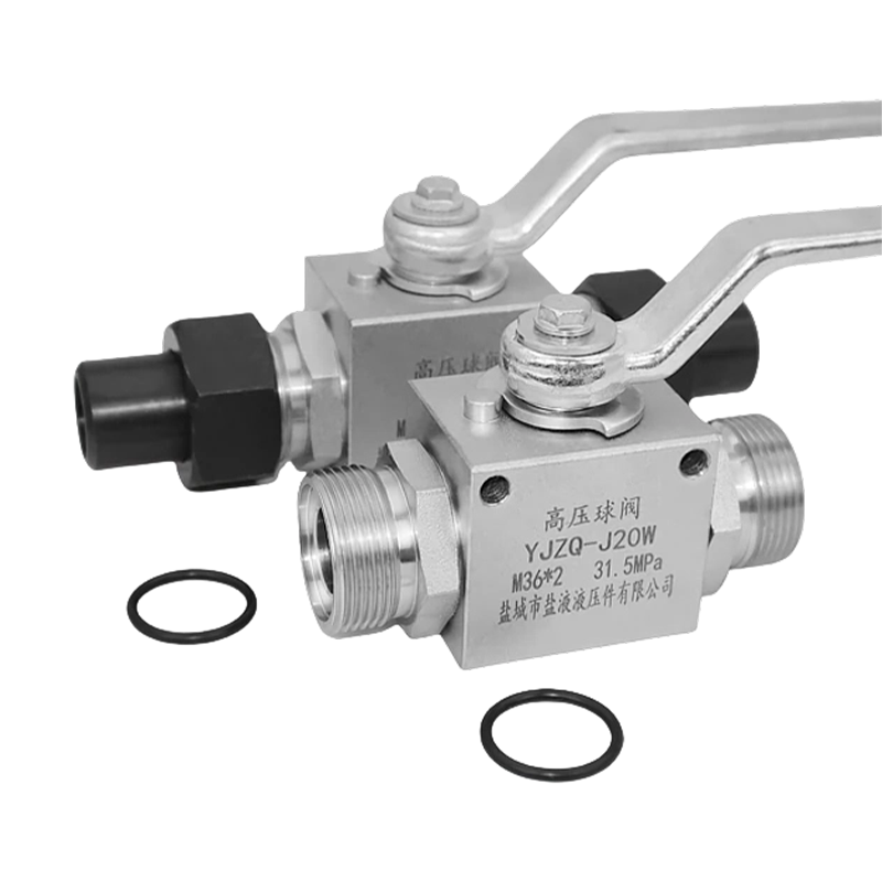 Wholesale KHB Hydraulic High-Pressure Ball Valve YJZQ Internal/External Thread WYancheng Yanye Hydraulic Parts Co., Ltd is China Custom KHB Hydraulic High-Pressure Ball Valve YJZQ Internal/External Thread Welded Ball ...View Product →
Never use a ball valve to regulate flow. A partially open ball leaves the sealing surfaces exposed to high-velocity oil, which erodes the seat and ball and destroys the valve's sealing function. Use a throttle, needle, or compensated flow control for regulation, and keep the ball valve as a pure open-close device.
Gate valves give a nearly unrestricted full-bore path and are common on large pipelines, but they are slow to operate. Globe valves are designed for throttling at the cost of a higher pressure drop. Butterfly valves are compact and lightweight for large-diameter, lower-pressure water or oil lines. For hydraulic systems, ball valves remain the preferred isolation choice because they combine a high-pressure rating, a clear open or closed position, and a tight seal.
The same valve body can behave very differently depending on how it is actuated. Actuation choice affects response time, fail-safe behavior, installation cost, and control precision.
| Actuation | Response | Best suited for | Notes |
|---|---|---|---|
| Manual lever | Slow, operator dependent | Process lines, emergency stop | No power required |
| Solenoid | Fast, tens of milliseconds | Automation and PLC control | Limited to small and medium flows |
| Pneumatic | Moderate | Medium flows, simpler installation | Needs clean compressed air |
| Hydraulic pilot | Fast and powerful | Large flows, remote control | Pilot pressure must be reliable |
| Proportional | Continuous, adjustable | Speed and force control in automation | Higher cost and more tuning required |
When you need to order or replace a hydraulic valve, work through this checklist in order. It prevents the three most common field mistakes: wrong pressure rating, wrong port thread, and wrong leakage class.
For a reference point on the shut-off side of hydraulic circuits, the main advantages of high-pressure ball valves explain why this family dominates isolation duty in hydraulic and gas lines.
Material selection affects corrosion resistance, cost, and service life. Sealing material matters just as much at high pressure, because a hardened or incompatible seal will leak long before the metal body fails.
| Material | Temperature range | Best suited for |
|---|---|---|
| Carbon steel | High strength | General hydraulic oil circuits with protective coating |
| 304 stainless steel | Good general corrosion resistance | Water, chemical, and food-adjacent lines |
| 316L stainless steel | Molybdenum improves chloride resistance | Marine, coastal, and aggressive media |
| NBR seals | -30 to +100 C | Standard mineral hydraulic oils |
| FKM seals | -20 to +200 C | High-temperature service and phosphate esters |
| PTFE seals | -100 to +260 C | Aggressive chemicals with mechanical seal support |
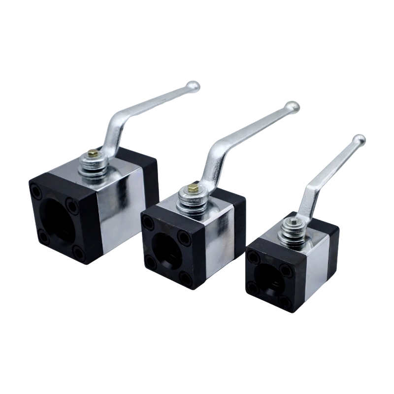
The suffix on a valve model communicates its rating: 320P and 400P denote 320 bar and 400 bar nominal working pressure respectively. Threaded stainless steel valves commonly cover this range. For larger flows, SAE flange ball valves handle high flow at high pressure with a connection that resists vibration and repeated disassembly.
Common hydraulic connection standards include:
A hydraulic valve rarely fails on its own. Dirt, heat, cavitation, and wrong settings cause most failures, and regular checks keep a circuit predictable.
| Symptom | Most probable valve cause | First action |
|---|---|---|
| Pressure below set value | Relief set too low, or spool and poppet wear | Verify with a calibrated gauge; recalibrate; then seat-check the valve |
| Pressure spikes and noise | Relief chatter or oversized directional valve | Adjust response, check valve sizing against flow |
| Cylinder drifts or drops | Counterbalance or check valve leaking, or set too low | Run a pressure decay test; reseat or replace the element |
| Speed changes with load | Simple throttle instead of a pressure-compensated flow control | Replace with a compensated flow control valve |
| Oil overheats | Relief passing continuously, or undersized throttle | Check the relief setting; measure pressure drop across the throttle |
A yearly maintenance routine for a hydraulic valve system should include:
Which hydraulic valve controls the direction of a cylinder? A directional control valve, normally a spool valve positioned by a lever, solenoid, or hydraulic pilot. For a double-acting cylinder, a 4/3 valve with a spring-centered spool is the standard choice.
What is the difference between a relief valve and a pressure reducing valve? A relief valve is normally closed and caps the maximum pressure of the circuit. A pressure reducing valve is normally open and holds the downstream pressure at a lower set value. They are not interchangeable.
Can a hydraulic ball valve regulate flow? No. A ball valve is a shut-off valve. Running it partially open erodes the ball and seat and destroys the sealing function. Use a throttle, needle, or pressure-compensated flow control valve for regulation.
What does the 320P or 400P marking on a valve mean? The number is the nominal working pressure in bar: 320P corresponds to 320 bar, and 400P to 400 bar. The letter P is a pressure class marker used on this valve family.
When should I use 316L stainless steel instead of 304? 316L contains molybdenum, which gives better resistance to chlorides, salt water, and aggressive chemicals. If the environment is coastal or the fluid is corrosive, 316L is the safer choice.
Why does my cylinder drift when the pump is off? Because a spool valve leaks internally, or a standard check valve opens under residual pressure. Use a pilot-operated check valve or a poppet-type shut-off element for load holding.
Every hydraulic circuit problem starts and ends at a valve. Match the pressure rating, choose the right functional family, and confirm the port standard, and you will eliminate most failures before the valve is installed.
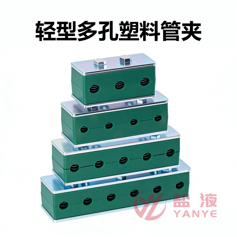
Yancheng Yanye Hydraulic Parts Co., Ltd. manufactures high-pressure ball valves, needle and stop valves, check valves, and pipe clamps used in hydraulic, natural gas, and petrochemical circuits. When you need a component for a specific pressure rating and connection standard, start with our full range of high-pressure ball valves, check valves, and hydraulic pipe clamps.
Recommended Products
Copyright © Yancheng Yanye Hydraulic Parts Co., Ltd. All Rights Reserved
Custom Ball Valve Factory
China Ball Valve Manufacturers




 English
  русский
  Español