HOME / NEWS / Industry News / Valve Actuator Guide: Types, Torque, Fail-Safe, Selection & Maintenance
2026-08-31
Content
A valve actuator is a mechanical device that automatically opens, closes, or throttles a valve using an external power source such as compressed air, electricity, or hydraulic fluid. If you have ever turned the handle of a manual ball valve, your arm was functioning as the actuator: delivering torque to the valve stem to rotate the ball through 90 degrees. When you replace that manual effort with a pneumatic cylinder, an electric motor, or a hydraulic piston attached to the same stem, the valve becomes an automated flow-control element that can be operated from a control room, a PLC, or a safety shutdown loop.
Actuators matter because industrial processes cannot rely on people turning handwheels quickly enough or consistently enough. Automated valves respond to signals in fractions of a second, hold exact positions for modulating control, and can be interlocked with trip systems. But the actuator is not a bolt-on afterthought: it must be sized and configured to match the valve's torque characteristics. The most common failures in actuated valve assemblies - stem damage, loose couplings, and valves that do not fully close - can almost always be traced back to an actuator that was too weak, too strong, or fitted with the wrong control accessories.
Valve actuators are grouped by the power source they use. For quarter-turn valves such as ball valves, the three main technical routes are pneumatic, electric, and hydraulic, with manual and spring-return arrangements as additions or fallbacks.
Pneumatic actuators use compressed air, usually delivered at 4 to 8 bar (0.4 to 0.8 MPa), to generate torque. For quarter-turn valves, two mechanical designs dominate: the rack-and-pinion and the scotch-yoke. A rack-and-pinion actuator moves two opposed pistons along a rack that drives a central pinion; its torque output is compact and smooth. A scotch-yoke actuator converts piston travel into rotation through a yoke, producing torque that increases toward the ends of the stroke - an advantage when a ball valve needs extra force to push the ball into the seat.
Pneumatic actuators are valued for speed, simple construction, and low purchase cost. A small rack-and-pinion actuator can stroke a DN25 ball valve in under 0.5 seconds. They are the first choice for basic on/off service on compressed air, water, oil, and gas lines. In high-pressure nitrogen and natural gas duty, a pneumatic actuator is often factory-integrated with the valve body, as with the 304 pneumatic high-pressure nitrogen ball valve, where the cylinder, valve body, and mounting flange are designed as one assembly.
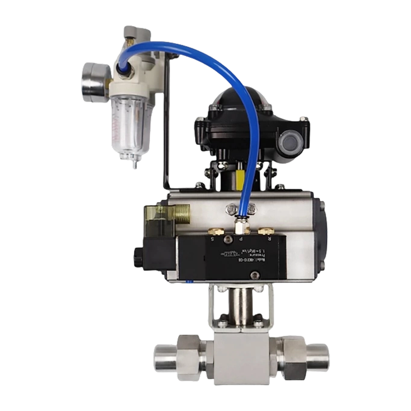 304 Pneumatic High-Pressure Nitrogen Ball Valve Suppliers, FactoryYancheng Yanye Hydraulic Parts Co., Ltd is China KHB-YJZQ series 304 pneumatic high-pressure nitrogen ball valve (internal/external threa...View Product →
Electric actuators drive the valve through an electric motor and a reduction gearbox. There are three families: multi-turn, for gate and globe valves; part-turn (quarter-turn), for ball and butterfly valves; and linear, for valves with a rising stem. A typical electric actuator contains a motor, a gear train, limit and torque sensors, a manual handwheel override, a control board, and an electrical connection compartment. Position feedback is generally a 4-20 mA or 0-10 V signal.
Electric actuators have overtaken pneumatic designs for many modulating duties because they position more accurately and need no air supply. They are slower on high-frequency cycling - a full stroke may take 5 to 30 seconds depending on motor speed and gear ratio - but they hold position without consuming power, a useful feature when the control system is offline. For processes that require precise throttling, the electric route is usually the right one.
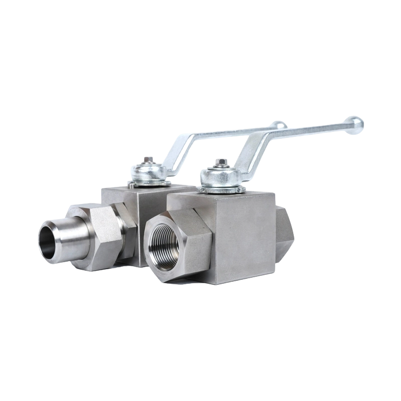
Hydraulic actuators use oil pressure, typically 70 to 350 bar, to produce torque or thrust. Because hydraulic fluid is nearly incompressible, a hydraulic actuator can hold a valve position precisely even when the pump stops, without energizing any brake. Hydraulic actuators are the heavy-duty option for large-diameter ball valves, subsea installations, and high-torque applications where a hydraulic power unit already exists. A hydraulic piston can deliver the same torque as a much larger pneumatic actuator, and response is fast because the working pressure is high. In hydraulic circuits, the valve body must be rated for the system pressure; the KHB hydraulic high-pressure ball valve with threaded and welded connections is a compact example designed to fit into dense hydraulic manifolds.
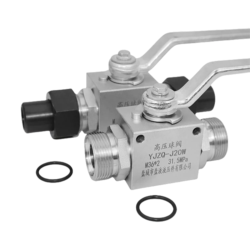 Wholesale KHB Hydraulic High-Pressure Ball Valve YJZQ Internal/External Thread WYancheng Yanye Hydraulic Parts Co., Ltd is China Custom KHB Hydraulic High-Pressure Ball Valve YJZQ Internal/External Thread Welded Ball ...View Product →
Manual operation never disappears completely. Most industrial actuators include a manual override - either a gear-driven handwheel or a removable handle - so the valve can be operated in the event of a power or air failure. Spring-return actuators take fail-safe one step further: a spring pack is compressed during the powered stroke and stores energy. When the power supply is lost, the spring pushes the valve to its fail-safe position, either closed (fail-closed) or open (fail-open), depending on the arrangement of the spring and the orientation of the valve.
The short answer to which type is best: it depends entirely on your duty, your existing utilities, and your required response time. To help with a shortlist, the table below compares the three main actuator types on the attributes that matter most in industrial valve service.
| Feature | Pneumatic | Electric | Hydraulic |
|---|---|---|---|
| Power source | Compressed air, 4-8 bar | AC/DC electric motor | Oil pressure, 70-350 bar |
| Typical torque range | 5 to 50,000 Nm | 10 to 200,000 Nm | Very high, custom built |
| Full-stroke time | 0.1 to 1 s (small bore) | 5 to 30 s typical | 0.5 to 5 s |
| Positioning accuracy | 0.5-2% with positioner | 0.1-1% | 0.5-2% |
| Fail-safe option | Spring return | Battery or spring pack | Accumulator |
| Best suited for | Fast on/off cycling | Precise modulating duty | Large valves, rough service |
The choice begins with the duty. If the line has an existing compressed air system, and the valve only needs to open and close, pneumatic is usually the lowest-cost route. If the process demands precise throttling and the facility already has reliable power, electric is cleaner. If the valve is large, the torque is high, and the plant has an HPU, hydraulic wins. Pairing that decision with the right valve body is equally important; the hydraulic ball valve buyer's knowledge base explains how valve porting and torque requirements align with actuator sizing.
The first engineering number you need is the valve's breakaway torque: the friction between the ball and the seat, plus the resistance of the stem packing, is usually highest when the valve is closed. Running torque is lower, and seating torque occurs just before the ball seats. Actuator catalogs publish a torque rating at a defined supply pressure; the actuator torque must exceed the highest valve torque with a safety margin. A pneumatic spring-return actuator is conventionally sized with a 1.4 to 1.5 safety factor; double-acting pneumatic can go to 1.3; electric actuators use at least 1.5. As a practical example: a high-pressure ball valve with a breakaway torque of 80 Nm and a spring-return pneumatic actuator should be rated at 80 x 1.4 = 112 Nm or more, measured at the plant's actual air supply pressure rather than at the catalog's nominal pressure.
Speed matters more than most buyers realize. Steam or gas shutdown lines may need full closure in under one second; clean water lines can tolerate several seconds. Pneumatic is the fastest family, electric is the slowest. If your process requires a specific stroke time, account not only for the actuator's internal speed but also for the time it takes to pressurize or vent the cylinder volume, plus the dead time of the solenoid valve or positioner.
Classify your application before choosing. A valve opened twice a day is open-close duty. A valve that cycles every few minutes is positioning duty. A valve that continuously throttles to maintain a setpoint is modulating duty and needs an actuator designed for high starting frequency. For pneumatic modulating service you also need a positioner - the device that compares the setpoint signal with the actual valve position and adjusts air pressure accordingly - because a bare cylinder cannot hold an intermediate position reliably.
The actuator operates in the same environment as the valve. Ambient temperature, humidity, rain, and the presence of flammable gas limit your shortlist. Common ingress protection ratings for outdoor use are IP65, meaning dust-tight and protected against water jets, and IP67, which adds temporary immersion. In a flammable atmosphere, the actuator motor and limit switch enclosure must be flameproof or intrinsically safe, and the wiring must enter through approved cable glands. At extremely low temperatures, be aware that condensed water in the airline can freeze; you may need a local heater on the positioner and solenoid valve.
Fail-safe is the behavior of the actuated valve when control energy is lost. Two definitions matter: the action (what the valve does) and the actuator configuration (how the valve is made to do it). For fail-closed, a spring-return pneumatic actuator pushes the ball closed when air pressure is released. For fail-open, the spring is arranged to push the ball open. For electric actuators, fail-safe can be achieved with a backup battery or a spring module that drives the motor to the end position; the battery version also enables remote communication during an outage. For hydraulic systems, an accumulator charged with nitrogen stores oil so the piston can stroke to the fail-safe position without the main pump running.
A useful rule: choose the fail-safe position based on the process hazard, not on convention. Fail-closed is standard for fuel or chemical feed lines where stopping the flow protects the process. Fail-open is correct for relief paths and for cooling water that must keep flowing to protect equipment. Document the required fail-safe time as well - for some trip applications, the specification is "closed within 2 seconds of the signal," which immediately rules out a slow electric actuator.
The actuator cannot do its job until it is correctly connected to the valve. Most modern valve actuators follow the ISO 5211 standard for the mounting interface, with a bolt pattern, pilot bore, and drive dimensions that match between the valve bonnet and the actuator flange. If you stick to ISO 5211, you can change actuator brands or upgrade from pneumatic to electric without machining a new adapter plate.
A quality mounting kit includes a bracket, a coupling, and bolts of the correct length and grade. The coupling transfers actuator torque to the valve stem, and its fit tolerances determine backlash. If the actuator drive is slightly larger than the valve stem, you need a machined bushing, not a shim. Poorly fitted couplings cause stem wear, seat leakage, and control oscillation. Also align the actuator so that the valve's open position matches the actuator's limit switch setting: a quarter-turn ball valve with the flow open at 0 degrees and closed at 90 degrees will confuse the control system if the actuator's cam is set at 92 degrees, because the limit switch will never trip.
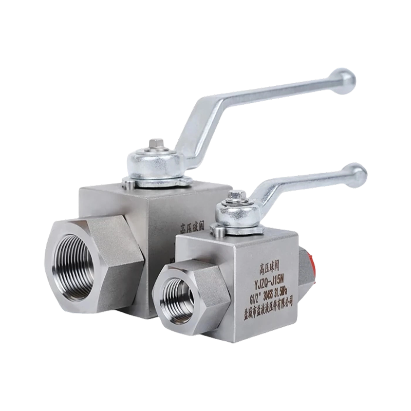
When automating a manual valve, start with a valve built for automated service. The 304/316L stainless steel internal-thread high-pressure ball valve is a compact example of a valve body that opens cleanly with modest actuator torque, has a consistent stem profile, and maintains a tight seal at working pressure. Mounting a pneumatic or electric actuator on it is straightforward when the valve is ordered with the correct mounting pad and stem extension.
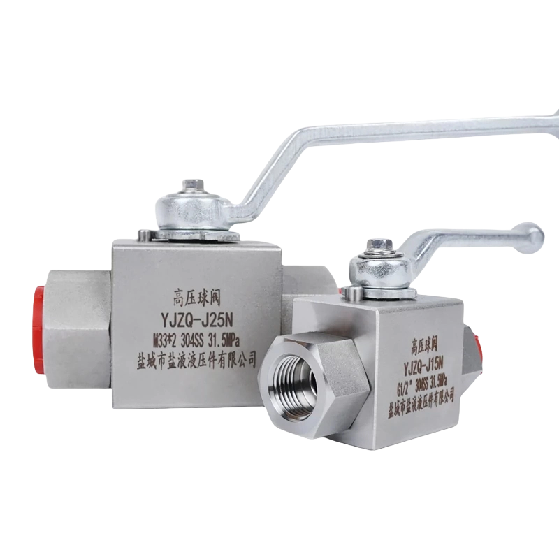 Wholesale KHB YJZQ 304/316L Stainless Steel Carbon Steel Internal Thread High-PrYancheng Yanye Hydraulic Parts Co., Ltd is China Custom KHB YJZQ 304/316L Stainless Steel Carbon Steel Internal Thread High-Pressure Ball...View Product →
For a full understanding of pressure ratings, materials, and connection types before you specify an actuator, the comprehensive ball valve buyer's guide covers the selection logic from the valve side, so that the valve and actuator arrive at the same specification sheet.
Actuated valve assemblies fail in predictable ways, and most failures can be prevented with a simple routine. Pneumatic actuators fail most often because of dirty air: water, oil, and particles degrade the seals and jam the piston. Keep a filter-regulator-lubricator (FRL) unit ahead of each actuator and drain it weekly. Electric actuators fail most often at the limit switches, the motor contactor, or the torque switch settings; these wear with the number of cycles, not the calendar. Hydraulic actuators fail at the rod seals and from oil contamination; check viscosity and filter condition at the power unit.
| Component | Check Interval | Typical Fault Symptom |
|---|---|---|
| Air line / FRL unit | Weekly | Water in bowl, pressure drop |
| Limit switches | Monthly | Signal drift, false indication |
| Valve stem coupling | Monthly | Backlash, worn drive corners |
| Spring pack | Annually | Corrosion, fatigue break |
| Positioner | Quarterly | Hunting oscillation, zero drift |
Also watch the interface between actuator and valve. If you see repeatable stem-seal leaks, or a valve that keeps drifting from its set position, check the actuator-to-valve coupling first; side load on the stem is the classic cause. For step-by-step direction on stem packing and seat integrity, the high-pressure ball valve operation and maintenance guide gives practical procedures that keep the automated assembly reliable over the long term.
Pneumatic uses compressed air, electric uses a motor, and hydraulic uses pressurized oil. Pneumatic is fast and economical for on/off service; electric is precise and clean for modulating service; hydraulic delivers the highest torque relative to its physical size and can hold position without continuous energy consumption.
Obtain the valve's breakaway torque from the manufacturer, then multiply by a safety factor of 1.3 to 1.5. Use the higher factor for spring-return pneumatic and electric actuators. Always verify the actuator's torque rating at the air pressure or supply voltage you actually have at the installation point, because a low supply pressure reduces the torque of any pneumatic actuator.
Yes, when it is fitted with a positioner and an air set. The positioner compares the incoming control signal with the actual valve position and adjusts the air pressure to hold intermediate travel points. Practical accuracy is roughly 0.5 to 2 percent of valve travel, which is adequate for many process temperature and flow loops.
Use a spring-return pneumatic actuator, a spring or battery pack on an electric actuator, or a hydraulic accumulator. The fail-safe action - closed or open - should be chosen from the process hazard analysis, not from the actuator supplier's default position.
Most industrial actuators include a manual override: a handwheel, an external hex shaft, or a lever. Confirm that the override can be engaged while the actuator is still pressurized, and check the handwheel torque rating against the valve breakaway torque, especially on high-pressure services where seating forces are substantial.
Recommended Products
Copyright © Yancheng Yanye Hydraulic Parts Co., Ltd. All Rights Reserved
Custom Ball Valve Factory
China Ball Valve Manufacturers




 English
  русский
  Español