HOME / NEWS / Industry News / Valve Automation Guide: Types, Benefits, Selection Criteria and Best Practices
2026-10-12
Content
A petrochemical facility in the Gulf region had to dispatch two operators per shift to manually throttle six high-pressure letdown valves. Each adjustment took roughly four minutes, and the downstream pressure drifted by up to 12 percent between corrections. After retrofitting those valves with pneumatic actuators and positioners linked to a distributed control system, the same adjustments became continuous, automatic, and held the setpoint within 1.5 percent. This is the core reason valve automation exists: not to eliminate the human, but to remove the variability and exposure that manual operation creates.
This article examines valve automation from the standpoint of an engineering buyer and a plant operator. It covers the definition and system architecture, the three actuator technologies, selection logic, communication options, high-pressure service considerations, and the maintenance factors that determine field reliability. The emphasis throughout is on practical engineering decisions rather than vendor marketing language.
The direct definition: valve automation is the addition of an actuator, a power supply, a feedback sensor, and a control interface to a valve so that the valve's position can be manipulated remotely, automatically, or both, without an operator physically turning the handwheel.
The boundaries matter as much as the actuator. A complete automated valve solution includes the actuation element, the control accessories, the connection to the process control system, and the mechanical mounting properly torqued to the valve stem.
What changes when you automate a valve:
A practical distinction: valve automation is different from valve control. Automation refers to the actuation package itself, making the valve remote-capable. Control refers to the loop that decides the position, such as PID logic, interlock logic, or a manual setpoint from a DCS. Most automated valves are also controlled valves, but a remotely switched open-close valve with limit switches is automated without being modulated.
The physical structure of an automated valve package can be broken down into four sub-systems, each with its own components, failure modes, and maintenance needs. Understanding the structure prevents the common error of buying an actuator purely on torque and ignoring everything else.
| Sub-system | Typical components | Primary job | Common failure mode |
|---|---|---|---|
| Actuator | Pneumatic cylinder, electric motor, hydraulic cylinder | Converts energy source into stem rotation or linear motion | Air leakage, motor burnout, seal wear |
| Control accessories | Solenoid valve, positioner, limit switches, boosters | Switch, modulate, and confirm valve position | Coil burnout, positioner calibration drift |
| Feedback instrument | Potentiometer, 4-20 mA transmitter, encoder | Reports true stem position to DCS or PLC | Signal drift, mechanical wear |
| Mounting and valve | Bracket, coupling, ISO 5211 flange, valve body | Transmits torque reliably to the flow element | Loose coupling, stem shear, seal aging |
The quality of the interface between these sub-systems determines field reliability more than any single component. For instance, a positioner that is not calibrated to the actuator's stroke curve will introduce oscillation even if the valve itself is completely healthy.
The selection of actuator technology is the highest-impact decision in any valve automation project. Each of the three main technologies has a distinct set of characteristics in terms of response speed, control accuracy, torque output, capital cost, and maintenance under field conditions.
Pneumatic actuators, typically rack-and-pinion or scotch-yoke designs, operate on filtered compressed plant air at 4 to 8 bar. They dominate process industry applications because of their speed, durability, and natural fail-safe options. A double-acting pneumatic actuator with a solenoid valve can cycle a quarter-turn ball valve in under one second; spring-return configurations provide automatic closing or opening on air failure.
The main drawbacks are the need for clean and dry compressed air infrastructure, position accuracy that depends on a positioner and typically lands at 0.5 to 2 percent, and torque output limited by supply pressure and cylinder size. For high-pressure nitrogen, natural gas, and hydraulic service in the 20 to 40 MPa class, pneumatic actuation remains popular because spring-return mode guarantees closure on supply failure and quarter-turn stroke characteristics are predictable.
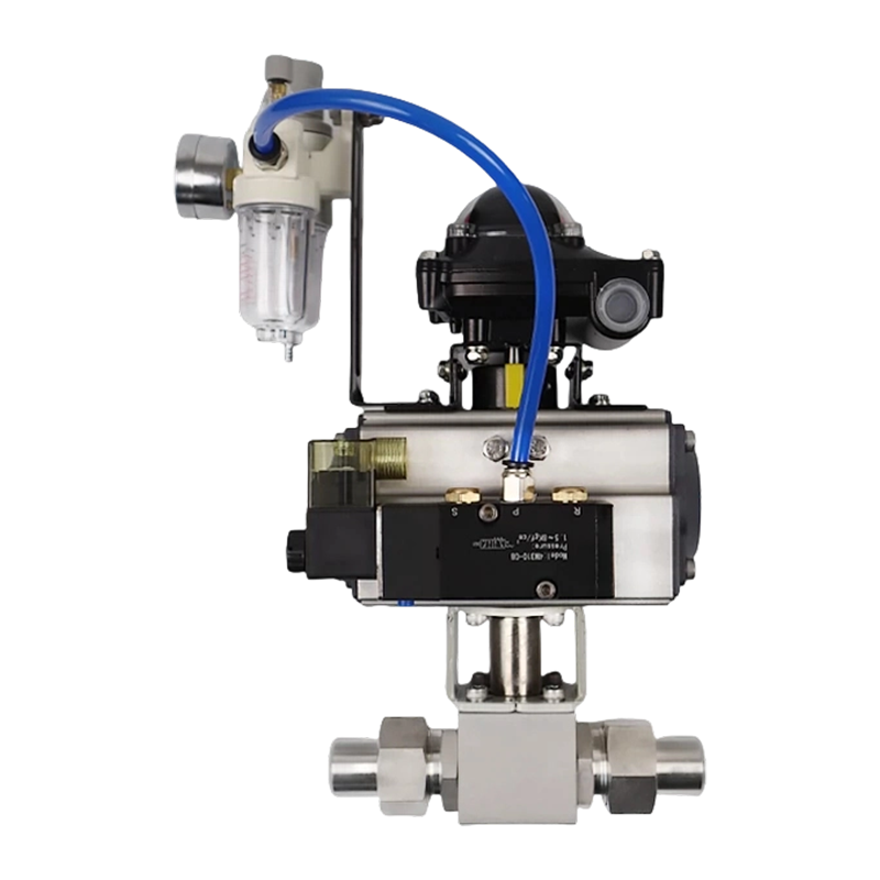 304 Stainless Steel Pneumatic High-Pressure Nitrogen Ball Valve with Thread OptionsThis valve combines corrosion-resistant stainless steel with pneumatic actuation for high-pressure nitrogen and inert gas applications up to 31.5 MPa, making it a reliable choice where remote control and spring-return safety are needed.View Product →
Electric actuators drive the valve through a motor and a reduction gearbox. Modern multi-turn and part-turn electric actuators with integrated variable frequency drive technology can position a valve almost as accurately as a hydraulic system, and their data-rich feedback makes them the preferred choice in remote locations and where compressed air is not available.
The downsides are slower response than pneumatic for large valves, more complex internal electronics, and fail-safe behavior that requires battery backup or spring-pack mechanisms that add significant cost.
Hydraulic actuators use pressurized oil to move the valve. They are used mostly for very high-torque applications, such as large main pipeline valves above 24 inches, or where the plant already has a hydraulic power unit for other machinery.
The main limitations are high capital cost and complexity of the power unit and oil piping, the risk of oil leaks that require containment measures, and a higher skill level required for maintenance.
| Attribute | Pneumatic | Electric | Hydraulic |
|---|---|---|---|
| Typical response time | 0.5 to 3 s | 3 to 30 s | 1 to 5 s |
| Positioning accuracy | 0.5 to 2 percent with positioner | 0.1 to 0.5 percent typical | 0.1 to 0.2 percent |
| Fail-safe capability | Spring return is standard | Battery or spring module | Accumulator necessary |
| Operating cost | Air consumption | Power only | Pump energy plus oil |
| Best fit | Process plants | Remote sites | Large mainline valves |
The decision to automate a valve should be justified in measurable terms. Field experience and industrial studies repeatedly show the same categories of benefit:
The point to internalize: valve automation is not a single benefit; it is several benefits that compound. A valve automated for remote switching also gives you position feedback that can be used for interlock logic; the same valve can later be placed in modulating service with only the addition of a positioner.
Selecting an automated valve is a multi-parameter engineering decision. The sequence below follows the decision path used by senior instrumentation engineers.
Manual, meaning a valve operated rarely, for example once a week for maintenance isolation. Automated on-off, meaning opened and closed multiple times per shift. Modulating, meaning continuously or frequently positioned to regulate a process variable. The duty determines the actuator category and the level of control accessories.
Valve torque varies with differential pressure, media, packing load, and operating frequency. The breakaway torque is almost always higher than the running torque, so always compare actuator output at the plant's minimum and maximum supply pressure with the valve manufacturer's breakaway torque at the most severe condition. A safety margin of 25 to 30 percent is standard practice for quarter-turn valves.
For most process services, the safest fail-safe is close on air or power failure. For cooling water supply or purge systems, the fail-safe is open. For some applications, the requirement is hold last position. Every automation package must have a defined failure mode. This is the single most important safety decision in the selection process.
The actuator mounting must follow the standardized valve-to-actuator interface defined by ISO 5211. Mismatched flange dimensions, drive coupling sizes, or incorrect engagement depth are common causes of stem damage. For threaded-body high-pressure valves, verify that the mounting bracket allows enough clearance for the gland nut and any compression fittings.
The minimal on-off package includes a solenoid valve for pneumatic or a motor starter for electric, plus two mechanical limit switches. For modulating service, add a positioner with 4 to 20 mA input and a position transmitter. Decide whether local manual operation is required during commissioning and emergencies; if yes, specify a declutchable manual override.
Ambient temperature range, exposure to rain or washdown, salty atmosphere in coastal plants, and hazardous area classification directly influence enclosure ratings and actuator material construction. A pneumatic actuator for a marine hydraulic line with aluminum housing needs a different anti-corrosion treatment than an electric actuator installed in a climate-controlled compressor room.
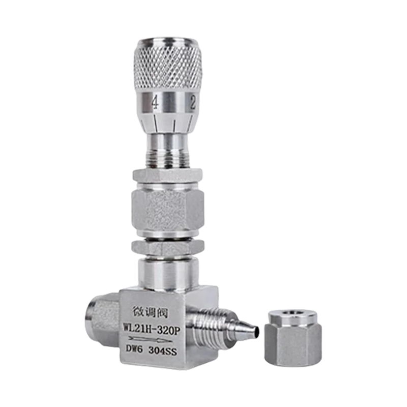 Stainless Steel Ferrule-Type Metering Needle Valve with Calibration ScaleDesigned for precise micro-flow adjustment in vacuum systems and high-pressure test benches, its multi-turn stem and graduated dial enable repeatable positioning, eliminating guesswork during commissioning and calibration.View Product →
For precision metering lines where calibration repeatability matters, selecting a ferrule-type metering needle valve with an integral calibration scale removes the guesswork from manual override and commissioning adjustments, especially in high-pressure test benches and gas blending skids.
The control path is what makes a valve automated rather than just remotely actuated. The standard evolution of plant control signals, from least to most information-rich, is summarized below.
| Layer | Typical signal | Information carried |
|---|---|---|
| Discrete | 24 V DC or 120 V AC dry contact | Open or close command from DCS or PLC |
| Analog | 4 to 20 mA current loop | Position setpoint and feedback |
| Digital fieldbus | HART, Foundation Fieldbus, PROFIBUS PA | Setpoint, position, diagnostics, configuration |
| Industrial Ethernet | EtherNet/IP, PROFINET | Two-way digital data, embedded web configuration |
| Wireless | WirelessHART, ISA100.11a | Position feedback in areas without cabling |
For buyer planning, the key rule: choose the communication layer before selecting the actuator and positioner, because retrofitting a fieldbus positioner into a plant installed on analog loops is sometimes possible but always more expensive than starting with the right protocol.
High-pressure systems introduce constraints that ordinary selection practice does not cover. Lines rated at 20 to 40 MPa, equivalent to 200 to 400 bar, are common in hydraulic systems, CNG and LNG stations, chemical injection systems, and high-pressure water jet service. When specifying automation for such valves, the following points are non-negotiable.
End connections determine the actuator's reaction forces. Threaded, welded, and flange-connected high-pressure valves all transmit reaction torque through the body. For threaded connections, the valve body must be wrenched against the line while the actuator torque signature is applied; otherwise the entire valve can unwind from the pipe.
Air supply filtration matters more at high cycles. Pneumatic accessories on high-pressure valves in gas service typically see more cycle counts per month than regular process valves. A dirty or wet supply line is the leading cause of solenoid valve and positioner failure in these applications.
Material selection for the valve body and actuator accessories. In high-pressure hydrogen sulfide or chloride-containing media, a standard carbon-steel bracket and bolts will corrode prematurely. Stainless steel or coated aluminum actuator housings are the correct choice for offshore and chemical service.
Precision calibration for small trim valves. High-pressure systems are unforgiving with regard to overshoot. A small volume flowing through a needle valve at 320 bar can raise downstream pressure very quickly. For this reason, operators of high-pressure test rigs and gas blending systems prefer needle valves with a calibration scale and fine-thread stem, which allow repeatable positioning to a fraction of a turn.
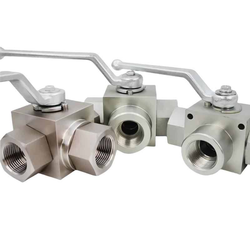
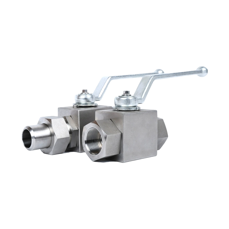
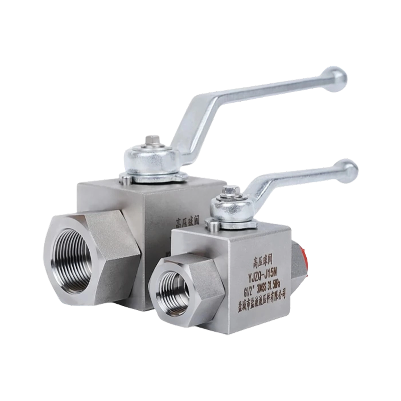
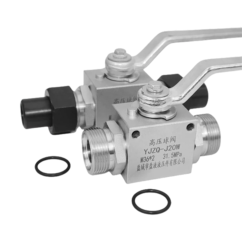 KHB Stainless Steel High-Pressure Ball Valve with Multiple Connection OptionsWith welded or threaded connections and a standardized quarter-turn drive, this valve simplifies actuator integration for automated high-pressure packages. Its robust construction handles harsh hydraulic and pneumatic systems reliably.View Product →
The KHB/YJZQ series high-pressure ball valve with internal thread, external thread, or welded connections is a common base element used in automated packages because its compact body and standardized quarter-turn drive make actuator mounting straightforward. When evaluating a high-pressure automation project, verify the valve's operating torque at the maximum rated pressure class, not the torque at the normal working pressure. For a deeper look at high-pressure ball valve procurement questions, the comprehensive guide tailored for ball valve buyers covers material, connection, and testing considerations.
The field reliability of an automated valve depends heavily on installation and maintenance practices. Maintenance records at many plants typically show that a valve automated with third-party components fails most often at the interfaces: loose coupling setscrews, leaking air tubing, drifted positioner calibration, and contact wear on limit switches.
| Interval | Action |
|---|---|
| Monthly | Inspect air tubing for leaks, check the positioner's filter, verify limit switch actuation. |
| Quarterly | Measure stroke time; a 10 to 15 percent increase compared with baseline indicates packing or actuator problems. |
| Annually | Disassemble and inspect the actuator's internal seals; replace O-rings. |
| Every two to three years | Recalibrate the positioner or replace it, and inspect the solenoid valve for coil burnout. |
Proper maintenance of automated valves is more discipline than technology. A well-documented baseline of stroke time, torque, and positioner input-output response lets a technician detect developing issues before the valve fails.
Valve automation is deployed in almost every plant that moves fluids, but the selection arguments differ by application:
A common thread in hydraulic and gas applications is that the valve itself must carry the pressure rating while the actuator package must be compact and robust enough for tight skids. That is precisely the niche that compact thread-type high-pressure ball valves and steel-braided pneumatic accessories fill.
Valve automation is the hardware system, consisting of the actuator, feedback, and wiring or piping that makes the valve remote-operable. Valve control is the decision-making part, such as PID loops, interlocks, or the manual setpoint from a DCS or PLC. Many references use automation for the complete package including control, but in engineering procurement, buyers distinguish between the actuator package, which is automation, and the logic that drives it, which is control.
Most quarter-turn valves such as ball and butterfly, and linear valves such as globe and gate, can be automated with the correct actuator and mounting kit. Restraints include insufficient stem height or anti-blowout design, excessive valve breakaway torque beyond practical actuator size, missing standardized mounting flange, and high-friction packing not designed for automated cycling. For high-pressure threaded-body valves, mountability is verified with the manufacturer before ordering.
The closing speed requirement varies by application and plant standard, but common specifications call for complete closure in 1 to 5 seconds. Pneumatic spring-return actuators with rapid-exhaust valves achieve this even on 6 to 12 inch quarter-turn valves. Electric actuators are generally not suitable for fast ESD closing unless equipped with spring-opened or spring-closed mechanisms, which are more expensive than pneumatic spring units.
Only if the valve is used for modulating service, where the position needs to be proportional to a setpoint or control signal. For simple open-close service, a solenoid valve plus limit switches is sufficient and more cost-effective. Positioners also serve a diagnostic function, so some plants choose them even on on-off valves to gain stroke and torque data.
You do not estimate from the valve spec alone. The valve manufacturer provides a measured or calculated required torque value, usually in newton-meters and, for high-pressure valves, at the maximum rated pressure. The actuator output torque must exceed that value by a safety margin of 25 to 30 percent, accounting for supply pressure variations, dynamic friction, aging of stem seals, and temperature effects.
Choose pneumatic when fast response is required, plant air is available and reliable, and the hazardous-area approval permits pneumatic devices. Choose electric when there is no reliable air supply, the site is remote with difficult access for maintenance, precision modulating control with diagnostics is required, and fast fail-safe action is not critical. For large mainline valves above moderate torque needs, hydraulic may be the right third option.
Valve automation is a well-established engineering practice, but its economic justification grows stronger every year as plants push for higher utilization, tighter process control, and fewer operators in hazardous areas. Start by classifying your valves by duty, fail-safe requirement, and environment; select components that can carry the torque of the stiffest condition; and invest in commissioning and maintenance discipline so the automation package stays reliable for its full service life.
For readers working on high-pressure ball valve packages specifically, the procurement insights and product details covered in the ball-valve buyer guide referenced above are a practical next step in the decision process.
Recommended Products
Copyright © Yancheng Yanye Hydraulic Parts Co., Ltd. All Rights Reserved
Custom Ball Valve Factory
China Ball Valve Manufacturers




 English
  русский
  Español